
Peripheral light amount correction apparatus, peripheral light amount correction method, electronic information device, control program and readable recording medium

a technology of peripheral light amount and correction apparatus, which is applied in the direction of exposure control, image enhancement, color signal processing circuit, etc., can solve the problems of inability to uniformly display light amount in the entire image screen, and inability to mount expensive lenses. , to achieve the effect of improving the yield of the whole digital camera product, poor mounting precision and low cost with precision

Inactive Publication Date: 2012-01-31
SHARP KK
View PDF21 Cites 17 Cited by
  • Summary
  • Abstract
  • Description
  • Claims
  • Application Information

AI Technical Summary

Benefits of technology

The solution effectively corrects insufficient peripheral light amounts and non-uniformities caused by lens precision issues, improving the yield of digital camera products by maintaining uniform luminance and allowing for precise correction without the need for additional inspection equipment.

Problems solved by technology

However, in an actual product, there is a case in which a lens and a light receiving face of an image capturing element cannot be set parallel to each other due to a distortion resulting from a precision of the lens itself or a poor mounting precision of the lens.
For example, a camera module mounted on such as a cell phone device cannot mount an expensive lens in consideration of cost, or mounting precision of the lens cannot be so high since the camera module is mass-produced.
In particular, when a lens is set tilted, a light amount in the entire image screen cannot be uniform for the image which is supposed to have the uniform light amount in the entire image screen.

Method used


Image

  • Peripheral light amount correction apparatus, peripheral light amount correction method, electronic information device, control program and readable recording medium
  • Peripheral light amount correction apparatus, peripheral light amount correction method, electronic information device, control program and readable recording medium
  • Peripheral light amount correction apparatus, peripheral light amount correction method, electronic information device, control program and readable recording medium

Examples


Embodiment Construction

[0118]Hereinafter, cases will be described with reference to the accompanying figures in which embodiments of a peripheral light amount correction apparatus and a peripheral light amount correction method according to the present invention are applied to a peripheral light amount correction circuit for a digital camera and a peripheral light amount correction method using the peripheral light amount correction circuit.

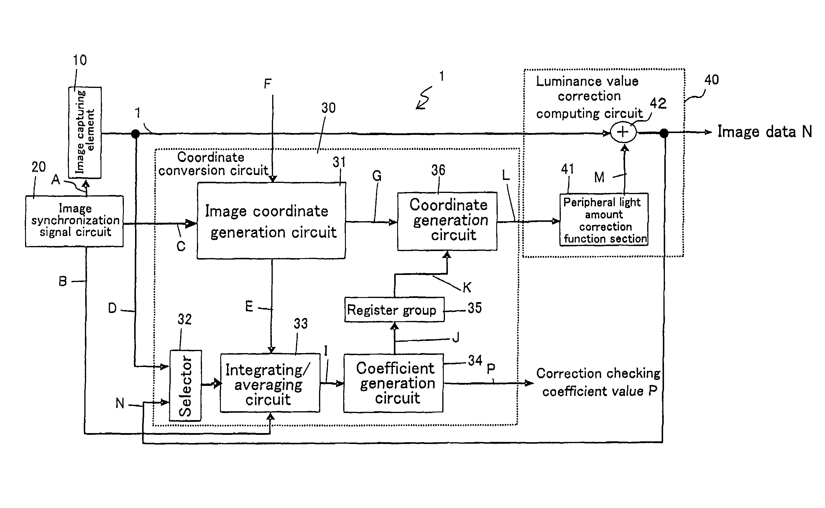
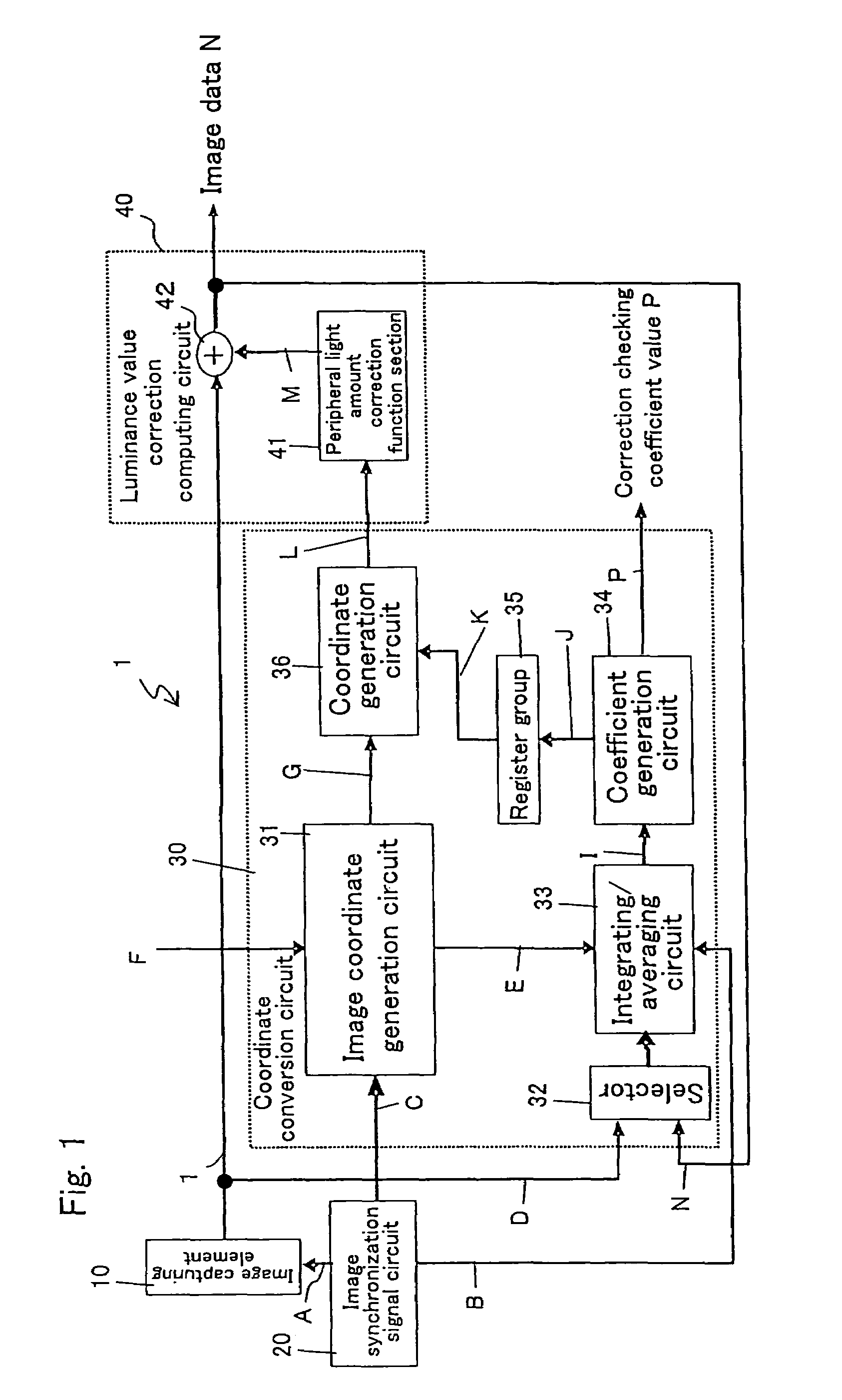
[0119]FIG. 1 is a block diagram showing an exemplary structure of a peripheral light amount correction circuit for a digital camera according to an embodiment of the present invention.

[0120]In FIG. 1, the peripheral light amount correction circuit 1 for the digital camera according to the present embodiment includes: an image synchronization signal generation circuit (image synchronization signal circuit) 20 as image synchronization signal generation means for outputting various image synchronization signals to an image capturing element 10 (e.g., CCD or CMOS image sen...


PUM


Abstract

The present invention corrects the insufficient peripheral light amount due to the lens shading and correcting the non-uniformity of light amount at the periphery due to a distortion resulting from a precision of the lens or a poor mounting precision of the lens. A peripheral light amount correction circuit is structured by an image synchronization signal generation circuit, a coordinate conversion circuit and a luminance value correction computing circuit. An integrated value of luminance values is calculated at the coordinate conversion circuit to extract light amount information. Coordinate values to be input to the luminance value correction computing circuit are generated based on an integrated / averaged value of the light amount information. In the luminance value correction computing circuit, peripheral light amount correction functions are converted based on the input coordinate values from the coordinate conversion circuit to perform appropriate correction on the input image.

Description

CROSS-REFERENCE TO RELATED APPLICATION(S)[0001]This application is a National Phase of International Application No. PCT / JP2006 / 322124 with an International Filing Date of Nov. 6, 2006, which claims priority to Japanese Application No. 2005-325201, filed on Nov. 9, 2005, where the above applications are incorporated by reference herein in their entireties.TECHNICAL FIELD[0002]The present invention relates to: a peripheral light amount correction apparatus for correcting a light amount at a periphery of an image capturing screen having a subject image captured thereon through an image capturing lens; a peripheral light amount correction method using the peripheral light amount correction method; an electronic information device, such as a digital camera (e.g., digital video camera and digital still camera), an image input camera, a scanner, a facsimile and a camera-equipped cell phone device having a digital camera module mounted thereon, using a solid-state image capturing device, i...

Claims


Application Information

Patent Timeline
Patent Type & Authority Patents(United States)
IPC IPC(8): H04N9/64H04N5/217H04N5/225G06K9/40H04N23/40H04N23/75H04N23/76
CPCG03B7/20G03B7/28G06T5/006H04N5/3572H04N2101/00H04N25/61G06T5/80H04N23/00H04N23/75
Inventor KAWASAKA, YASUKI
Owner SHARP KK
Learn More