
Diversity combining iterative decoder

a decoder and diversity technology, applied in the field of wireless digital communication systems, can solve the problems of inability to match the performance, limited approach, unusable signals for receivers, etc., and achieve the effect of reducing the probability of error of output signals and less errors

Inactive Publication Date: 2012-01-31
CSR TECH INC
View PDF8 Cites 5 Cited by
  • Summary
  • Abstract
  • Description
  • Claims
  • Application Information

AI Technical Summary

Benefits of technology

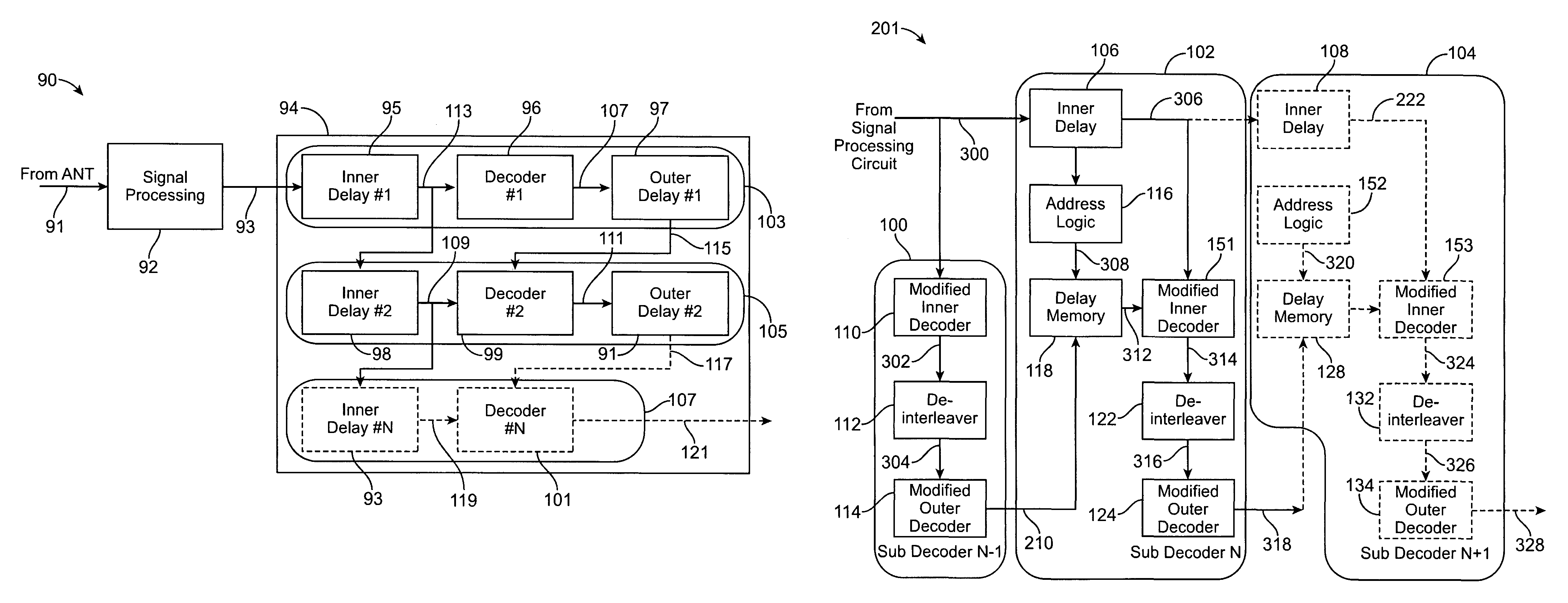
[0015]Briefly, in one embodiment of the present invention, an iterative decoder circuit includes an N number of sub-decoders, N−1 of the sub-decoders each being responsive to a baseband signal from one of M number of signal processing circuits. Each of the N−1 number of sub-decoders includes, an inner delay responsive to a baseband signal provided by a corresponding signal processing circuit for generating an inner delayed signal, a modified decoder that receives the inner delayed signal and generates a set partition signal, some of which have less errors than previous set partition signals. An Nth inner delay is responsive to the baseband signal and provides an Nth inner delayed signal. An Nth modified decoder is responsive to the Nth inner delayed signal and to the set partition signal and provides an output signal, wherein the probability of error of the output signal is reduced by correcting errors in some of the set partition signals.

Problems solved by technology

Some antenna orientations may render the signal unusable by the receiver.
Although block-based selection cannot match the performance of maximal ratio combining, especially for the case of a flat additive white Gaussian noise (AWGN) channel, it provides significant gain over the single antenna case for many practical scenarios.
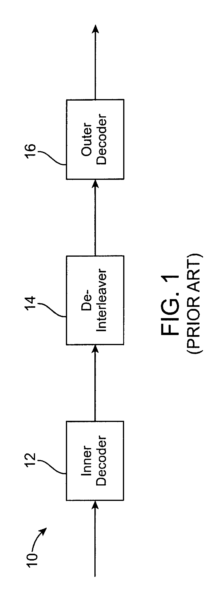
However, this approach is limited in that the output of one decoder cannot be used to influence another decoder's operation.
However, these traditional receivers typically operate several dB away from the Shannon limit for their respective data rates and signal bandwidths.
Part of this difference can be attributed to limitations of the trellis and Reed Solomon (RS) codes themselves.
However, a significant part of this difference is due to the traditional decoder architecture, which does not fully utilize the power of the trellis and RS codes.
A limitation in the foregoing prior art system is that the re-encoding process can have infinite memory, so an error in the outer decoder output can cause the re-encoded output to be wrong from that point forward.
However, this is not the case in many transmission systems, including that defined in ATSC A / 53.
Although some information from the outer decoder is used to improve inner decoder performance, this technique does not fully utilize all of the information.
The primary cost associated with this gain is the extra memory required to store delayed inputs and perform re-interleaving.
Each decoder iteration, in the foregoing technique, requires a large amount of extra memory, and no mechanism is provided for trading off memory size and performance for a given number of iterations.

Method used


Image

  • Diversity combining iterative decoder
  • Diversity combining iterative decoder
  • Diversity combining iterative decoder

Examples


Embodiment Construction

[0034]To overcome the limitations in the prior art described above, and to overcome other limitations that will become apparent upon reading and understanding the present specification, the present invention discloses an apparatus and method for decoding a signal received from an antenna or from multiple antennas using iterative decoding techniques to cause reduced bit-error rate at low signal to noise ratios while reducing memory requirements. Noise, as used herein, refers to undesirable data or data that is not supposed to be a part of the signal that was transmitted and sought to be received, rather it is without meaning.

[0035]These and various other advantages and features of novelty which characterize the invention are pointed out with particularity in the claims annexed hereto and form a part hereof. However, for a better understanding of the invention, its advantages, and the objects obtained by its use, reference should be made to the drawings which form a further part hereo...


PUM


Abstract

An iterative decoder circuit includes an N number of sub-decoders, N−1 of the sub-decoders each being responsive to a baseband signal from one of M number of signal processing circuits. Each of the N−1 number of sub-decoders includes, an inner delay responsive to a baseband signal provided by a corresponding signal processing circuit for generating an inner delayed signal, a modified decoder that receives the inner delayed signal and generates a set partition signal, some of which have less errors than previous set partition signals. An Nth inner delay is responsive to the baseband signal and provides an Nth inner delayed signal. An Nth modified decoder is responsive to the Nth inner delayed signal and to the set partition signal and provides an output signal, wherein the probability of error of the output signal is reduced by correcting errors in some of the set partition signals.

Description

BACKGROUND OF THE INVENTION[0001]1. Field of the Invention[0002]The present invention relates generally to wireless digital communication systems and particularly to receivers employed in such systems and including iterative decoder.[0003]2. Description of the Prior Art[0004]In wireless digital communication systems, the orientation of the receive antenna can have a major impact on receiver performance. Some antenna orientations may render the signal unusable by the receiver. One well-known approach to overcome this problem is the use of “antenna diversity.” This involves receiving the same transmit signal with two or more receive antennas, and combining the signals in the receiver. The combined signal in this type of receiver generally has a higher probability of being decoded correctly than either of the constituent signals alone.[0005]The optimum approach for combining signals in a diversity receiver is called “maximal ratio combining.” This approach is well-known in the art, and...

Claims


Application Information

Patent Timeline
Patent Type & Authority Patents(United States)
IPC IPC(8): H03M13/00
CPCH03M13/253H03M13/2936H03M13/3746H03M13/6306H03M13/6538H04L1/005H04L1/006H04L1/0065
Inventor COOKMAN, JORDAN CHRISTOPHERDONG, PINGYU, TAO
Owner CSR TECH INC
Learn More