Magnetic assembly for loading and conveying ferrous metal articles

Active Publication Date: 2012-02-07
BUNTING MAGNETICS
View PDF4 Cites 9 Cited by
  • Summary
  • Abstract
  • Description
  • Claims
  • Application Information

AI Technical Summary

Benefits of technology

[0009]By configuring the conveyor or pulley component of the instant inventive assembly as a permanent magnet having opposing curved conveyor belt supporting north and south poles, magnetic flux (i.e., the magnetic field chara

Problems solved by technology

A common drawback or deficiency of such magnetic conveyor pulley and conveyor belt combinations is an insufficiency or deficit in the magnetic strength and density of lines of magnetic flux which extend from the pulley at the conveyor's end.
As a result of such deficiency, such common magnetic pulley and conveyor combinations have only a limited capability to attract and convey away ferrous magnetic parts and scrap materials.
Such ma

Method used


Image

  • Magnetic assembly for loading and conveying ferrous metal articles
  • Magnetic assembly for loading and conveying ferrous metal articles
  • Magnetic assembly for loading and conveying ferrous metal articles

Examples


Example

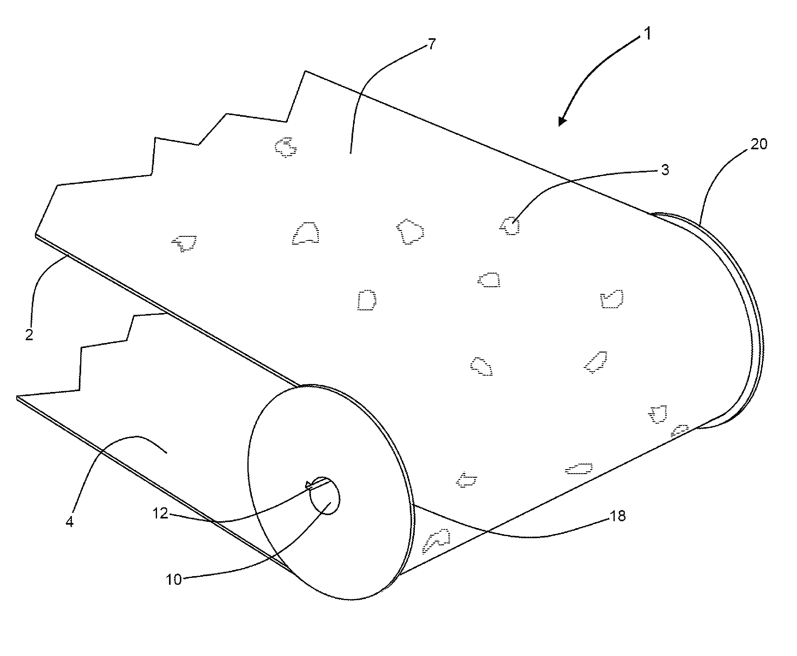
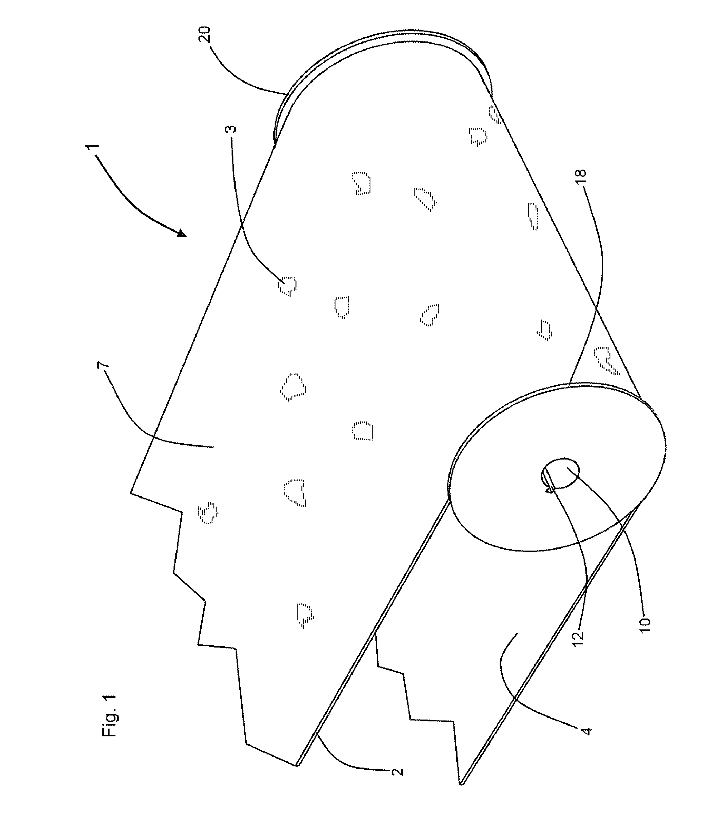
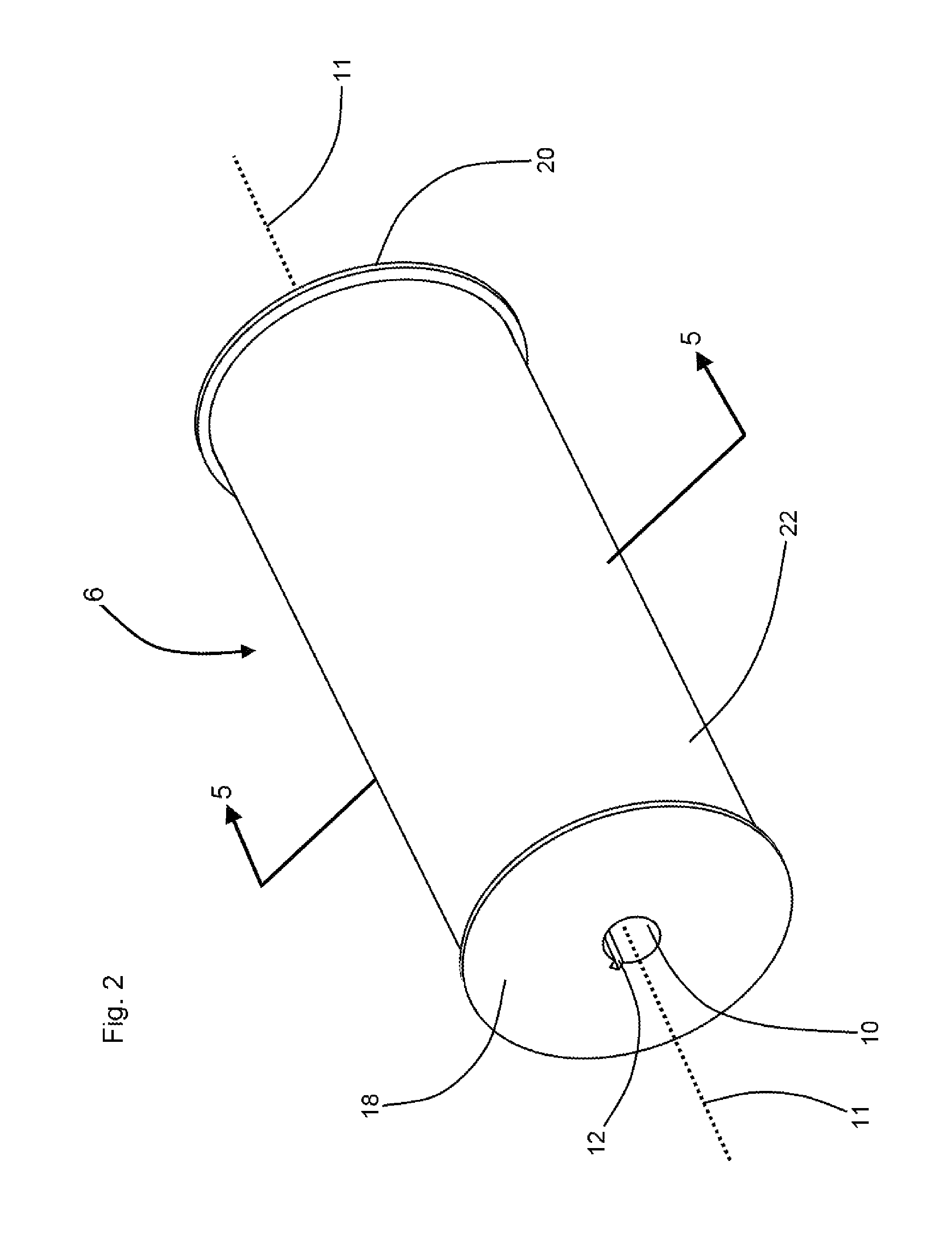
[0020]Referring now to the drawings, and in particular to Drawing FIGS. 1 and 2, a preferred embodiment of the instant inventive assembly for loading and conveying ferrous metal articles is referred to generally by Reference Arrow 1. A major structural component of the assembly 1 comprises a permanent magnet which is referred to generally by Reference Arrow 6. The magnet 6 dually functions as a conveyor pulley having a rotation axis 11 and as means for attracting ferrous metal articles 3. In a preferred embodiment, referring further simultaneously to FIGS. 3 and 5, an axle shaft receiving sleeve 8 is aligned concentrically about and along the rotation axis 11, such sleeve 8 forming an axle shaft receiving bore 10. To facilitate transmission of rotary power from an axle shaft (not depicted within views) received within bore 10, a key slot 12 is provided. Alternatively, referring further simultaneously to FIG. 2A, an alternatively configured magnet component 6A presents journal axles ...


PUM


Abstract

An assembly for loading and conveying ferrous metal articles including a magnet having north and south poles, an axis between the north and south poles, the poles forming an annular belt support; a powered conveyor belt extending over the belt support for rotating the magnet, the magnet being segmented along the polar axis, a first polar axis segment being a magnet mounting plate, a plurality of second polar axis segments being sub-magnets, each such sub-magnet overlying or underlying the magnet mounting plate having north and south poles, and having a polar axis, and a third polar axis segment being a sheath extending annularly about the magnet's first and second polar axis segments, the sheath having a radially outer surface forming the magnet's annular belt support.

Description

FIELD OF THE INVENTION[0001]This invention relates to combinations of mechanical belt conveyors and magnetic rolls and pulleys. More particularly, this invention relates to combinations of such machinery for automatically loading and conveying ferrous articles such as scrap steel and small steel parts.BACKGROUND OF THE INVENTION[0002]Turn back pulleys or rollers of powered continuous loop belt conveyors are known to be specially adapted to include embedded or internally housed permanent magnets. Where such turn back rollers or pulleys are so adapted, they advantageously cause the continuous loop conveyor to additionally perform an automatic ferrous metal attracting and loading function. Where, for example, such a magnetically adapted conveyor pulley is positioned over a moving stream of materials (or a relatively moving stream of materials resulting from movement of the conveyor assembly) ferrous metal parts and / or scrap steel contained within the stream are advantageously drawn out...

Claims


Application Information

Patent Timeline
IPC IPC(8): B65G15/30B65G15/58
CPCB65G15/58B65G21/2018H01F7/021
Inventor SUDERMAN, DONALD A.VOORHEES, BARRYSCOTT, PAUL
Owner BUNTING MAGNETICS
Why Eureka
Try Eureka