Rotational atherectomy device with fluid inflatable support elements and distal protection capability

a technology of distal protection and atherectomy device, which is applied in the field of rotational atherectomy device, can solve the problems that the drive shaft of any rotational atherectomy device with distal protection advanced over a guidewire may still be too large to cross very tight stenotic lesions

Active Publication Date: 2012-02-07
CARDIOFLOW
View PDF55 Cites 35 Cited by
  • Summary
  • Abstract
  • Description
  • Claims
  • Application Information

AI Technical Summary

Benefits of technology

[0105]An anchoring sleeve may be disposed around the torque transmitting coil at least along a length of the drive shaft occupied by fluid inflatable support elements , said anchoring sleeve being disposed over the coil under the fluid impermeable membrane which forms the distal fluid inflatable support element, the fluid impermeable membrane along a length of the fluid inflatable support elements being bonded to the anchoring sleeve only along one side of a circumference of the drive shaft, thereby preventing the fluid inflatable support elements from expanding uniformly around an entire circumference of the anchoring sleeve when fluid inflated so as to form a fluid inflated counterweights with centres of mass spaced radially away from a longitudinal axis of the torque transmitting coil and the lumen of the drive shaft in a direction opposite to the direction in which a centre of mass of the abrasive element is spaced away from the longitudinal axis of the torque transmitting coil and the lumen of the drive shaft.

Problems solved by technology

The outer diameter of the drive shaft of any rotational atherectomy device with distal protection which is advanced over a guidewire may still be too large to cross very tight stenotic lesions.

Method used


Image

  • Rotational atherectomy device with fluid inflatable support elements and distal protection capability
  • Rotational atherectomy device with fluid inflatable support elements and distal protection capability
  • Rotational atherectomy device with fluid inflatable support elements and distal protection capability

Examples


first embodiment

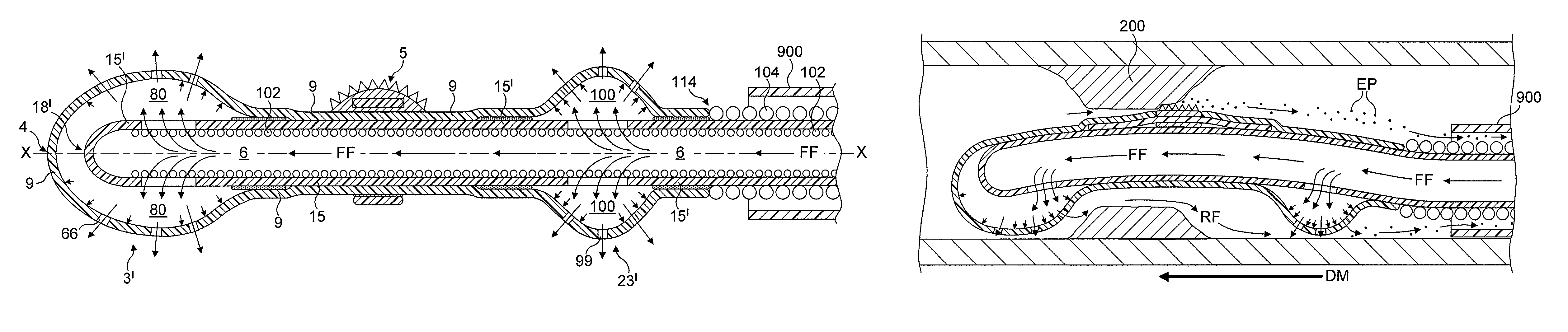
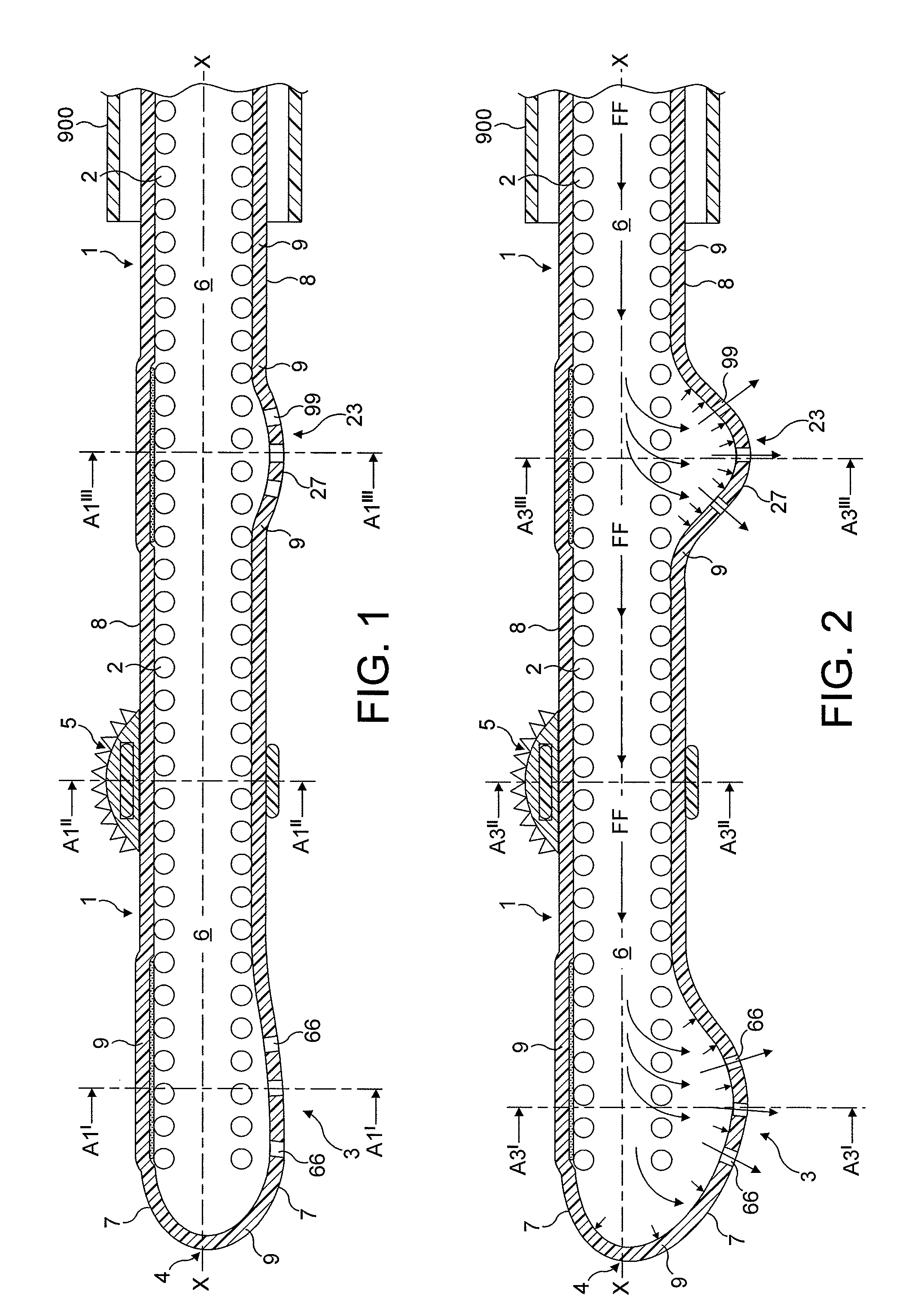
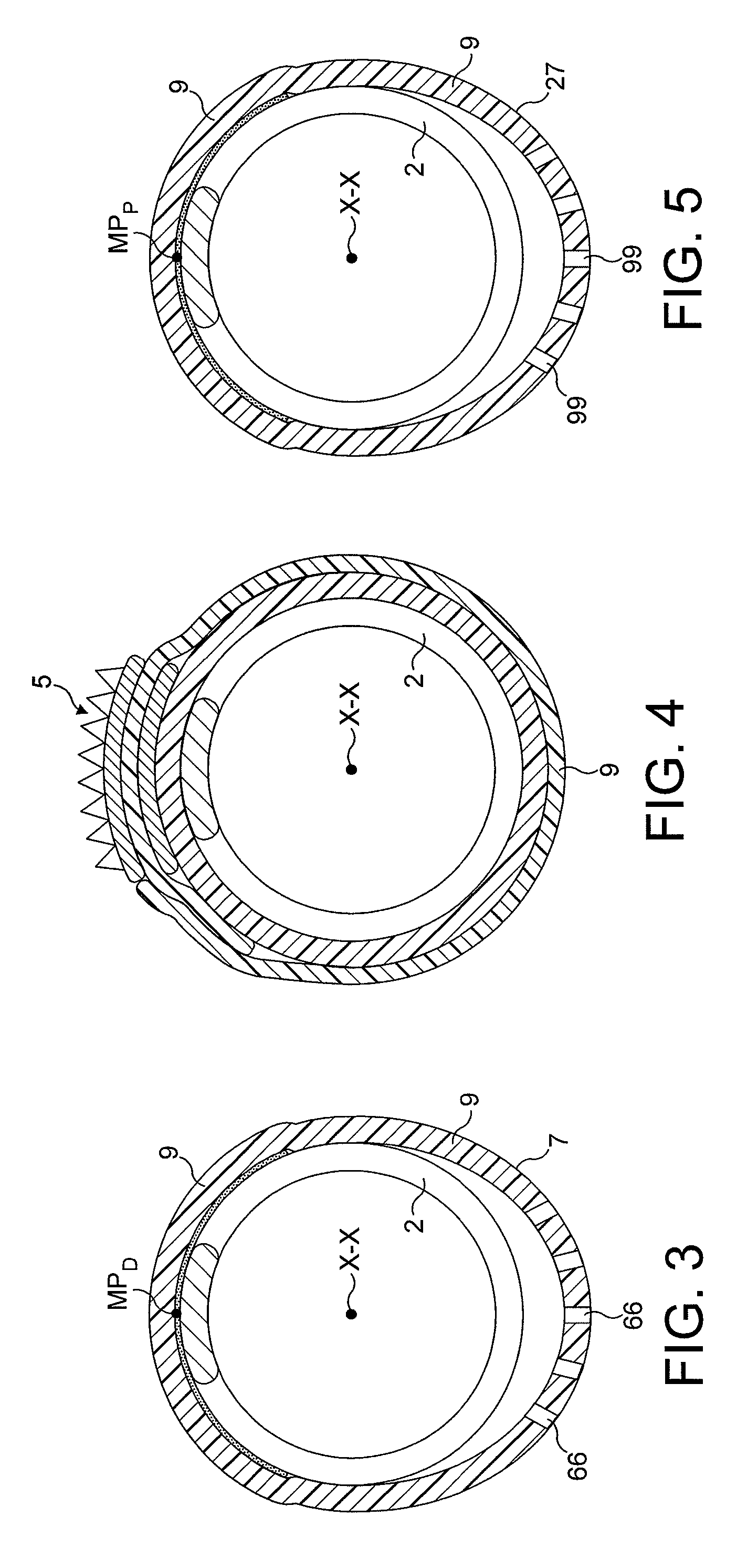
[0154]FIGS. 1 through 8 illustrate in longitudinal and transverse cross-sections a distal end portion of the rotational atherectomy device of the invention. The rotational atherectomy device is comprised of a rotatable, flexible drive shaft 1, a distal fluid inflatable support element 3 located at a distal end 4 of the device and an abrasive element 5 mounted to the drive shaft 1 proximal to and spaced away from the distal fluid inflatable support element 3. The drive shaft 1 comprises a torque transmitting coil 2. The abrasive element 5 and the distal fluid inflatable support element 3 are rotatable together with the drive shaft 1. The drive shaft 1 includes a long lumen 6 for the transport of pressurized fluid to the distal fluid inflatable support element 3. In FIGS. 1 to 8, a wall 7 of the distal fluid inflatable support element 3 and a wall 8 of the long lumen 6 of the drive shaft 1 are formed from a single fluid impermeable membrane 9. The fluid impermeable membrane 9 extends ...

second embodiment

[0163]FIGS. 11 to 18 illustrate the first modification of the device in which the anchoring sleeve 15 extends in a proximal direction towards the proximal end of the drive shaft 1. The anchoring sleeve 15 forms the wall of the lumen 6 of the drive shaft 1 and therefore should be made from a fluid impermeable material.

[0164]FIGS. 19 and 20 illustrate a second modification of the second embodiment of the device in which the anchoring sleeve 15 extends around the torque transmitting coil 2 only along a distal end portion 20 of the drive shaft 1. The fluid impermeable membrane 9 extends from the distal end of the device towards the proximal end of the drive shaft 1. FIGS. 19 and 20 show that the fluid impermeable membrane 9 may alone form the wall of the lumen 6 of the drive shaft 1 proximal to a proximal end 30 of the anchoring sleeve 15.

[0165]FIGS. 1 to 20 illustrate the embodiments of the device in which the distal end of the drive shaft 1 coincides with the distal end 12 of the torq...

third embodiment

[0182]FIG. 41 shows yet another modification of the device. The embodiment of FIG. 41 is similar to the embodiment of FIG. 27 except that the core element 300′ shown in FIG. 41 comprises a long lumen 330 configured for transferring pressurized fluid into the lumen 6 of the drive shaft through an opening 333 located in a wall of the (hollow) core element 300′. The opening(s) 333 are located adjacent to a distal end 337 of the (hollow) core element 300′. FIG. 42 shows the device of FIG. 41 in which pressurized fluid is flowing from the lumen 330 of the core element 300′ into the lumen 6 of the drive shaft 1 such that a layer of fluid is formed between the wall of the core element 300′ and the wall of the drive shaft 1 of the rotational atherectomy device. FIG. 43 shows the device of FIG. 42 in which the core element 300′ is being withdrawn from the lumen 6 of the drive shaft 1 and the device. It should be noted that continuous flow of the pressurized fluid from the lumen of the core e...


PUM


Abstract

A rotational atherectomy device for abrading a stenotic lesion from a vessel of a patient comprises a flexible drive shaft (1) which extends towards a distal end of the device, a distal fluid inflatable support element (3, 3″) located at a distal end of the drive shaft and an abrasive element (5) mounted to the drive shaft proximal to and spaced away from the distal fluid inflatable support element. Both the abrasive element and the distal fluid inflatable support element are rotatable together with the drive shaft and the drive shaft comprises a torque transmitting coil (2) which defines a long lumen of the drive shaft. The distal fluid inflatable support element is formed from a fluid impermeable membrane (9, 9″) that crosses a longitudinal axis (x-x) common to the torque transmitting coil and the lumen of the drive shaft at the distal end of the device, thereby preventing pressurized fluid flowing along the lumen of the drive shaft from entering the vessel in the direction of said longitudinal axis so that fluid has to pass through the fluid inflatable support element, inflating said support element and exiting from the device through an outflow opening (66) in the fluid inflatable support element in a direction different from the direction of the longitudinal axis of the coil and the lumen.

Description

CROSS-REFERENCE TO RELATED APPLICATIONS[0001]This application is a national phase application based on PCT / EP2007 / 062777, filed Nov. 23, 2007, the content of which is incorporated herein by reference, and claims priority of GB Patent Application No. 0623366.2, filed Jul. 13, 2006, the content of which is incorporated by herein by reference.BACKGROUND OF THE INVENTION[0002]1. Field[0003]The present invention relates to a rotational atherectomy device for removing or reducing stenotic lesions in blood vessels such as a human artery by rotating an abrasive element within the vessel to partially or completely ablate the unwanted material.[0004]2. Description of the Related Art[0005]Atherosclerosis, the clogging of arteries, is a leading cause of coronary heart disease. Blood flow through the peripheral arteries (e.g., carotid, femoral, renal etc.), is similarly affected by the development of atherosclerotic blockages. One conventional method of removing or reducing blockages in blood ve...

Claims


Application Information

Patent Timeline
Patent Type & Authority Patents(United States)
IPC IPC(8): A61B17/22
CPCA61B17/320758A61B17/320725A61B17/22A61B2017/22052A61B2017/22054A61B2017/22068A61B2017/22071A61B2217/005A61B2217/007A61M1/0084A61B2017/320004A61B2034/107A61M1/85A61B17/32002A61B2017/00557A61B2017/320032A61B2017/320766
Inventor SHTURMAN, LEONID
Owner CARDIOFLOW
Why Eureka
Try Eureka