Hydraulic control module for vehicle transmission and diagnostic detection method for the same

a technology of vehicle transmission and hydraulic control module, which is applied in the direction of hybrid vehicles, electric propulsion mountings, instruments, etc., can solve problems such as affecting the reliability and durability of transmission

Active Publication Date: 2012-02-14
GM GLOBAL TECH OPERATIONS LLC
View PDF12 Cites 19 Cited by
  • Summary
  • Abstract
  • Description
  • Claims
  • Application Information

AI Technical Summary

Benefits of technology

[0009]The present invention provides advanced hardware diagnostic detection for the clutch control components in a hydraulic control module of a multi-mode hybrid transmission. The detection scheme utilizes pressure switch sensors to detect the position of each of the valves associated with the clutch control mechanization. The mechanization of these sensors with the valves provides the ability to clearly define the position of each of the valves, while also enabling the transmission electro-hydraulic control module (TEHCM) to diagnose the state of health of each pressure switch. This will allow the diagnostics to differentiate between a failed switch and a failed (e.g., “stuck” or “out of position”) valve.
[0010]One of the primary benefits of this invention is the ability to safely diagnose the clutch control components in a power transmission. That is, a TEHCM operating in accordance with the present invention can systematically identify the position and state of health of each of the clutch control valves and, from that, determine what clutches are available to ensure that any undesired clutches are locked out and unable to apply during vehicle operation. The detection scheme of the present invention prevents unexpected and undesired shift sequencing within the transmission.

Problems solved by technology

The lubricating and cooling capabilities of transmission oil systems greatly impact the reliability and durability of the transmission.

Method used


Image

  • Hydraulic control module for vehicle transmission and diagnostic detection method for the same
  • Hydraulic control module for vehicle transmission and diagnostic detection method for the same
  • Hydraulic control module for vehicle transmission and diagnostic detection method for the same

Examples


Embodiment Construction

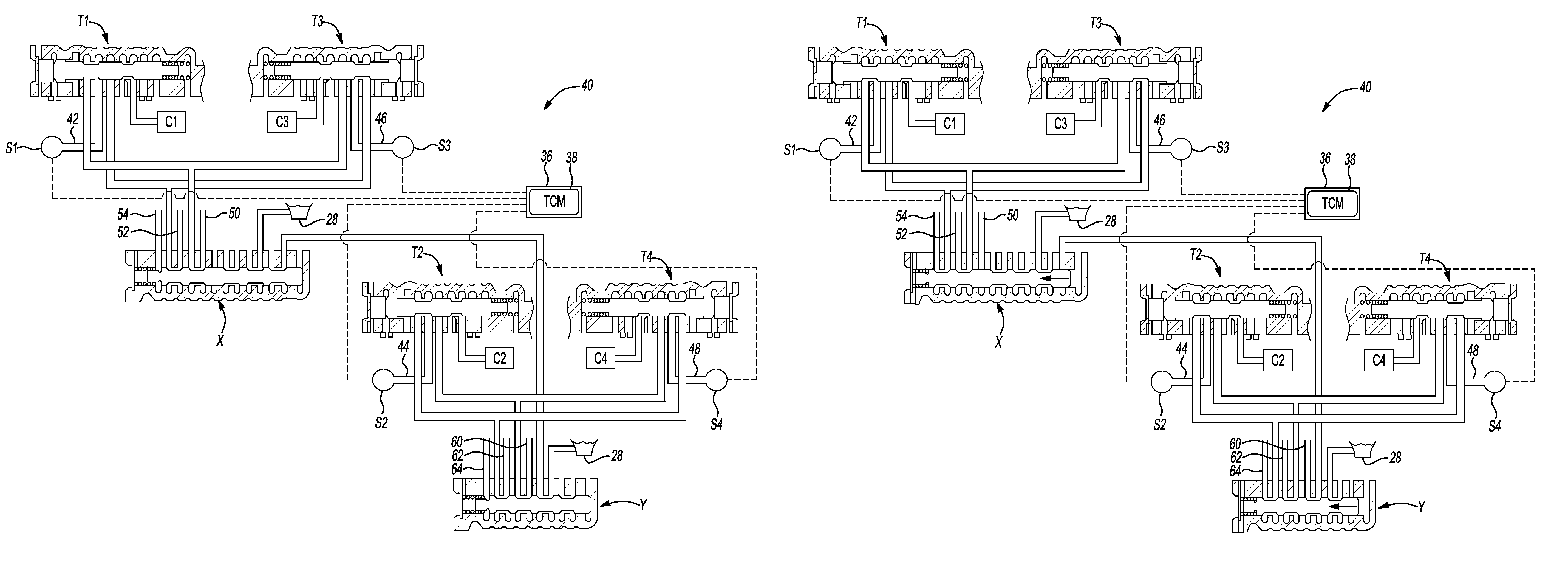
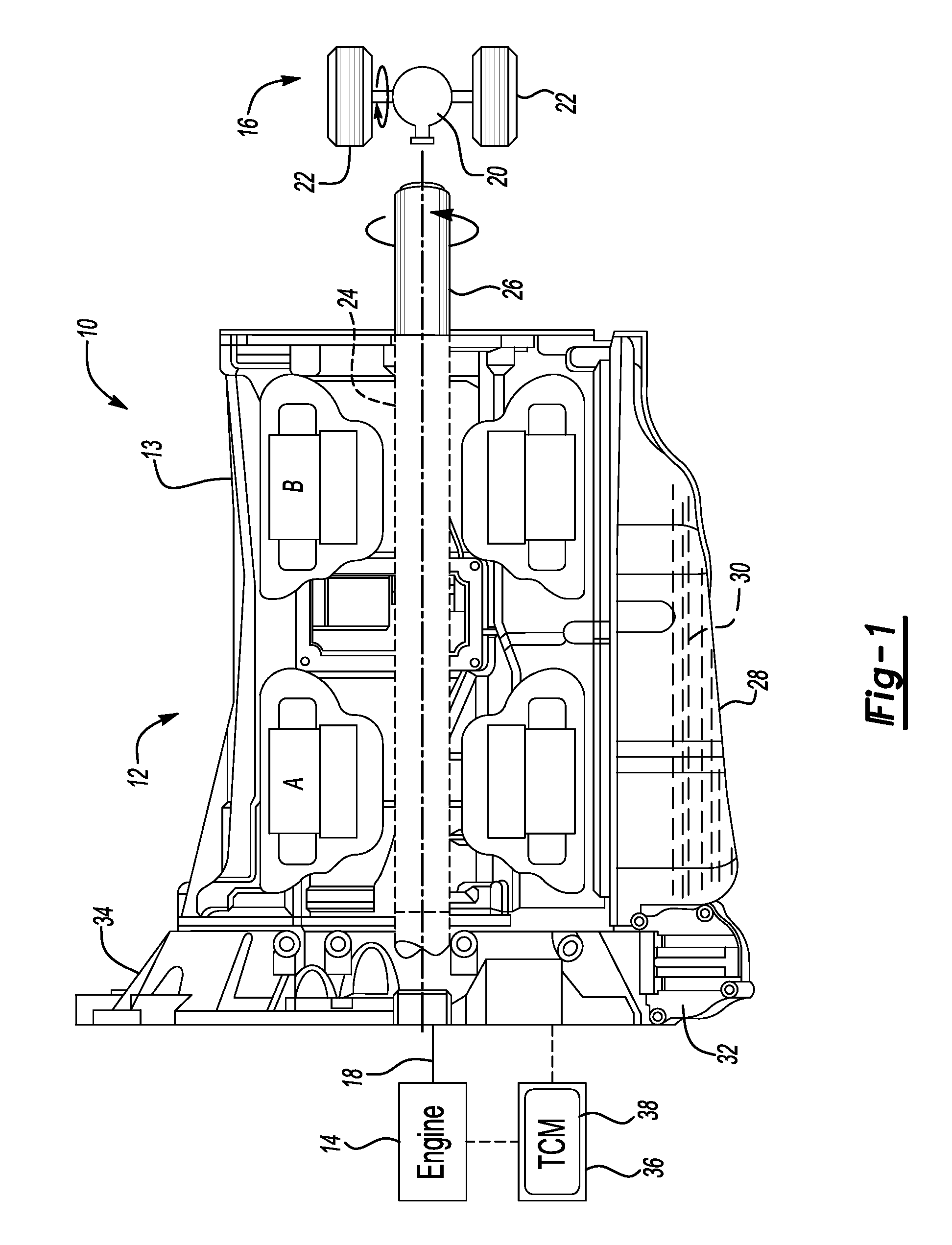
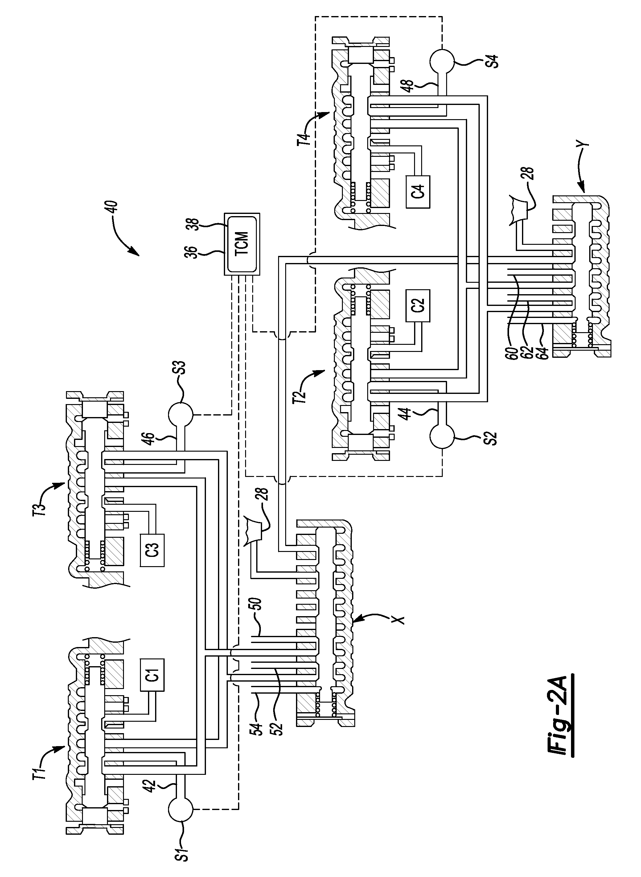
[0036]The present invention is described herein in the context of the multi-mode hybrid-type powertrain having a multi-speed power transmission shown in FIG. 1. The hybrid powertrain illustrated in FIG. 1 has been greatly simplified, it being understood that further information regarding the standard operation of a hybrid power transmission (or a hybrid-type vehicle for that matter) may be found in the prior art. Furthermore, it should be readily understood that FIG. 1 merely offers a representative application by which the present invention may be incorporated and practiced. As such, the present invention is by no means limited to the particular arrangement illustrated in FIG. 1.

[0037]Referring to the drawings, wherein like reference numbers refer to like components throughout the several views, there is shown in FIG. 1 a schematic depiction of an exemplary vehicle powertrain system, identified generally as 10, having a restartable engine 14 drivingly connected to, or in power flow...


PUM


Abstract

A detection scheme for diagnosing failure of clutch control components in a hydraulic control module of a power transmission utilizes pressure switch sensors to detect the position of each of the valves associated with the clutch control mechanization. The mechanization of these sensors with the valves provides the ability to clearly define the position of each of the valves, while also enabling the transmission electro-hydraulic control module (TEHCM) to diagnose the state of health of each pressure switch. The detection scheme may then differentiate between a failed switch and a failed (e.g., “stuck” or “out of position”) valve, while preventing unexpected and undesired shift sequencing within the transmission.

Description

CLAIM OF PRIORITY AND CROSS-REFERENCE TO RELATED APPLICATION[0001]This application claims the benefit of and priority to U.S. Provisional Patent Application No. 61 / 042,451, filed on Apr. 4, 2008, which is hereby incorporated by reference in its entirety.TECHNICAL FIELD[0002]The present invention relates generally to motorized vehicle powertrains, and more specifically to hydraulic control modules for vehicle transmissions, and diagnostic detection methodologies for the same.BACKGROUND OF THE INVENTION[0003]In general, motorized vehicles, such as the conventional automobile, include a powertrain that is comprised of an engine in power flow communication with a final drive system (e.g., rear differential and wheels) via a multi-speed power transmission. Hybrid type powertrains generally employ an internal combustion engine (ICE) and one or more motor / generator units that operate either individually or in concert to propel the vehicle. That is, power output from the engine and motor / ge...

Claims


Application Information

Patent Timeline
Patent Type & Authority Patents(United States)
IPC IPC(8): F16H61/16G06F17/00F16H61/18G06F7/00
CPCB60K6/445B60K6/547B60W10/115F16D48/066F16H61/12B60K6/365B60K1/02Y10T477/69363B60W20/00F16D2500/1066F16D2500/3024F16D2500/506F16D2500/5108F16H2061/1208F16H2061/1224F16H2059/683F16H2061/1264Y02T10/6239Y10S477/906Y10T477/75Y10T477/6934Y02T10/62B60W10/02B60W20/50
Inventor FOSTER, MICHAEL D.
Owner GM GLOBAL TECH OPERATIONS LLC
Why Eureka
Try Eureka