Wave-powered water wheel type generator

a generator and wave technology, applied in the direction of electric generator control, rotors, vessel construction, etc., can solve the problems of large number of machines and large maintenance burden, and require considerable surface area

Inactive Publication Date: 2012-02-21
NEESE STEPHEN L
View PDF42 Cites 35 Cited by
  • Summary
  • Abstract
  • Description
  • Claims
  • Application Information

AI Technical Summary

Benefits of technology

[0008]The instant invention overcomes these problems. It is a Styrofoam-filled plastic cylinder that has collapsible paddle wheel fins attached about the circumference. A shaft runs through the cylinder and extends from the two ends. The shafts are held by bearings. The bearings are attached to a frame structure that is embedded into the seabed. The frame has supports that are designed to move up and down with the flow of the tide to keep the cylinder at the mean water level at any given time. The shafts then extend past the bearings and are connected to a generator, or, if necessary, to a gear drive system that, in turn, connected to generators or other mechanical devices.

Problems solved by technology

Although these devices work, they require considerable surface area to lay out the pattern of floats to generate sufficient power.
Finally, the number of machines creates a large maintenance burden.

Method used


Image

  • Wave-powered water wheel type generator
  • Wave-powered water wheel type generator
  • Wave-powered water wheel type generator

Examples


Embodiment Construction

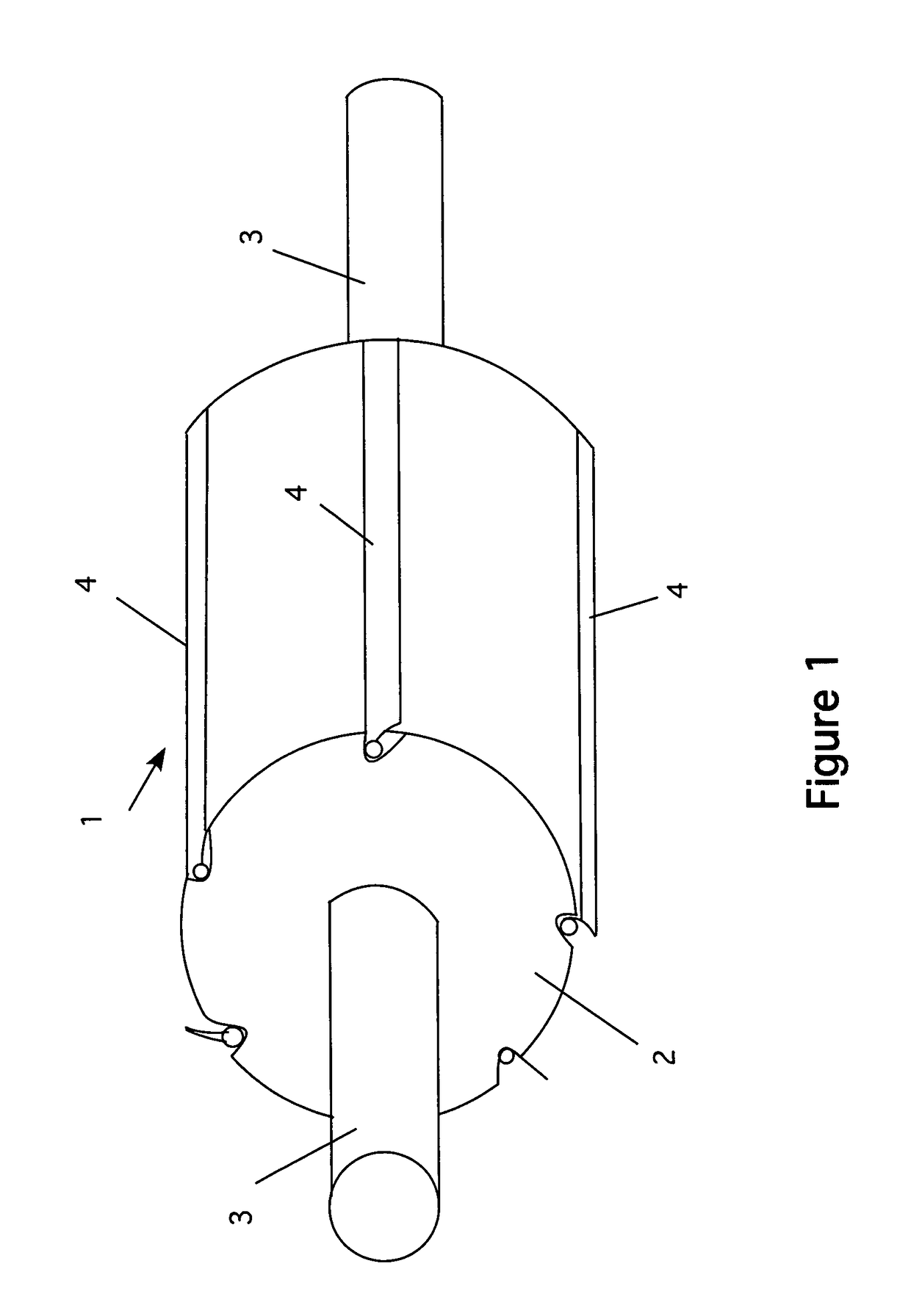
[0016]Referring now to FIG. 1, a perspective view of the device 1 is shown. The device is made of a lightweight cylinder 2 that is made of Styrofoam or a similar lightweight material. In the preferred embodiment, the Styrofoam is covered with a strong plastic cover that protects the core from damage. The cylinder has a shaft 3, which passes through its center and extends from the ends, as shown. About the perimeter of the cylinder 2, are a number of pivoting blades 4 (see also FIG. 2). FIG. 1 shows a six-blade configuration, although the device can have more blades, as is discussed below. As shown if FIG. 1, the blades 4 run the entire length of the cylinder.

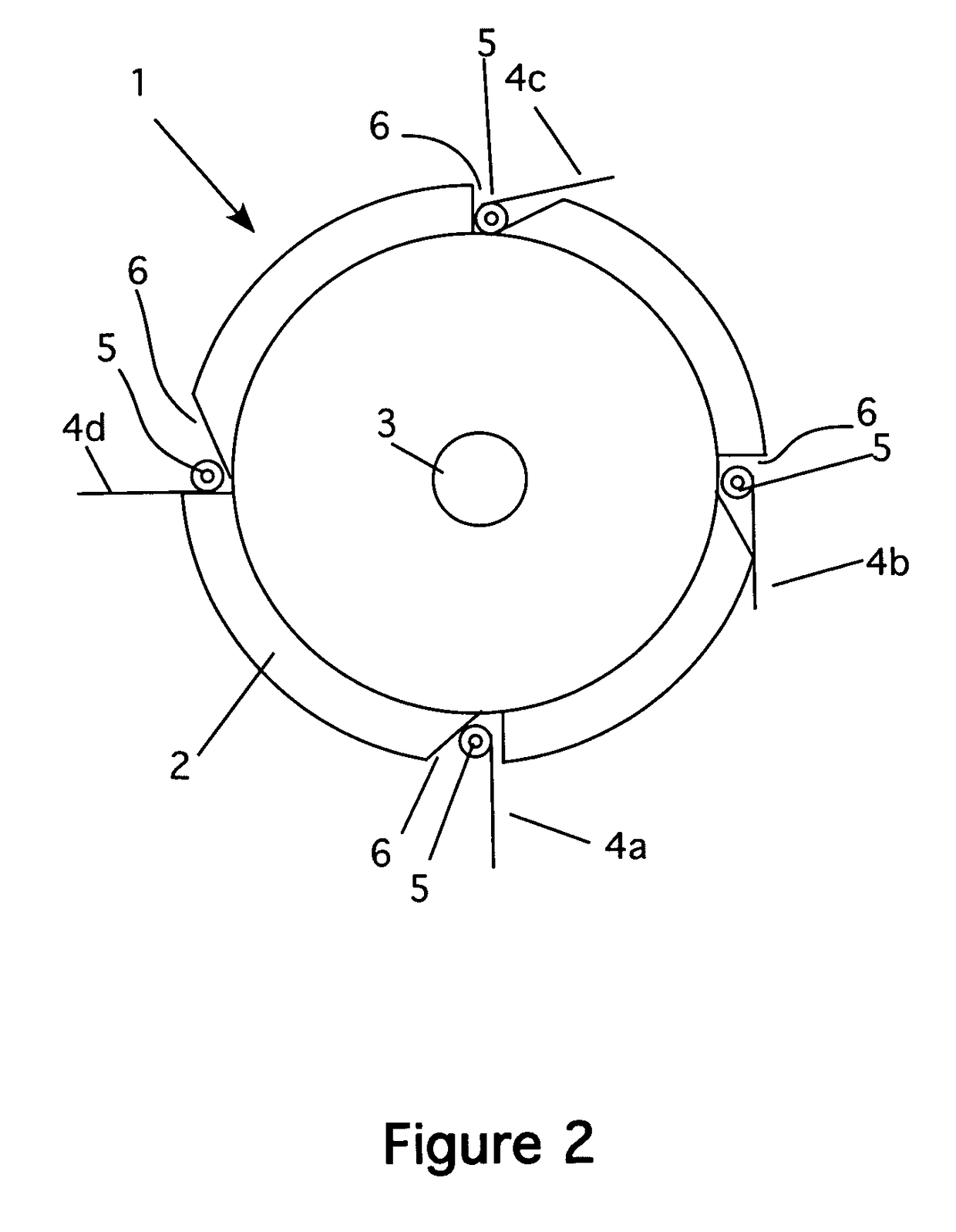
[0017]FIG. 2 shows an end view of the device 1 in a four-blade configuration. Note that each blade 4 is attached to the cylinder 2 using a hinge 5. In this way, the blade can move about as shown in the figure. Note also that the cylinder has a receiver notch 6 formed at each blade location. The shape of the notch is designed res...


PUM


Abstract

A Styrofoam-filled plastic cylinder that has collapsible paddle wheel fins attached about the circumference. Two shafts extend from the ends of the cylinder. The shafts are held by bearings. The bearings are attached to a frame structure that is embedded into the seabed. The shafts then extend past the bearings and are connected to a gear drive system that, in turn, connected to generators or other mechanical devices. When installed in the sea, the cylinder will turn in the swells/tidal action for as long as the ocean produces waves. Platforms on either side of the cylinder rise and fall with tidal action to maintain effective contact with the water at all times. Moreover, because the structure is positioned at or near the water surface, maintenance is much simpler for this device.

Description

CROSS REFERENCE TO RELATED APPLICATIONS[0001]Not ApplicableSTATEMENT REGARDING FEDERALLY SPONSORED RESEARCH AND DEVELOPMENT[0002]Not ApplicableBACKGROUND OF THE INVENTION[0003]1. Field of the Invention[0004]This invention relates to a wave-powered generator and particularly to a wave powered generator using a lightweight paddle wheel configuration.[0005]2. Description of the Prior Art[0006]Water-powered generators have been in use for centuries, going back to the old waterwheels used to power mills. For example, U.S. Pat. No. 647,638 shows a wave motor that has a number of buckets placed on an ovular path. This is set in the surf and is driven by wave action. The movement of the buckets is used to drive a motor or similar device. U.S. Pat. No. 889,153 teaches a current motor that is placed in a tidal current and power is produced as the device is turned by the movement of the currents.[0007]In recent years, a surge of interest in using tidal surges and wave action to generate power ...

Claims


Application Information

Patent Timeline
Patent Type & Authority Patents(United States)
IPC IPC(8): F03B13/00H02P9/04F03B13/12F03B13/10B63H3/00
CPCF03B13/183F03B13/262H02P9/04B63B2035/4466F05B2240/915Y02E10/38Y02E10/30
Inventor NEESE, STEPHEN L.
Owner NEESE STEPHEN L
Why Eureka
Try Eureka