Device for delivering a reducing agent to an exhaust system of an internal combustion engine

Inactive Publication Date: 2012-02-28
ROBERT BOSCH GMBH
View PDF21 Cites 5 Cited by
  • Summary
  • Abstract
  • Description
  • Claims
  • Application Information

AI Technical Summary

Benefits of technology

[0008]For attaining this object, it is proposed according to the invention that between the feed pump and the exhaust system, an additional metering device be provided, which delivers reducing agent, pumped continuously by the feed pump, to the exhaust system intermittently and thus takes on the quantity metering function. This embodiment makes it possible on the one hand to use time-tested conventional feed pumps without a quantity-metering function, which not only can be procured economically but also are resistant to reducing agent, such as a mixture of urea and water, and are proof against ice pressure. On the other, the feed pump can operate during the entire period of operation of the internal combustion engine, so that control of the pump can be dispensed with, which not only leads to cost savings but also, because of the sturdier construction of such feed pumps, also assures less vulnerability to malfunction. Moreover, the feed pump can optionally also be driven directly by the engine.
[0014]To make the metering device resistant to ice pressure, so that it will not be damaged as a consequence of an expansion in volume of freezing reducing agent, such as a mixture of urea and water, in the metering device, the pressure line and / or the intake line inside the metering device are surrounded at least in part by elastically deformable compression bodies, which are compressed in the expansion in volume, caused by freezing, of the reducing agent and in this way assure a marked drop in the freezing pressure.

Problems solved by technology

This means that a sufficient pressure that exceeds the opening pressure of the nozzle cannot build up upstream of the nozzle, and thus the nozzle remains closed.

Method used


Image

  • Device for delivering a reducing agent to an exhaust system of an internal combustion engine
  • Device for delivering a reducing agent to an exhaust system of an internal combustion engine

Examples


Embodiment Construction

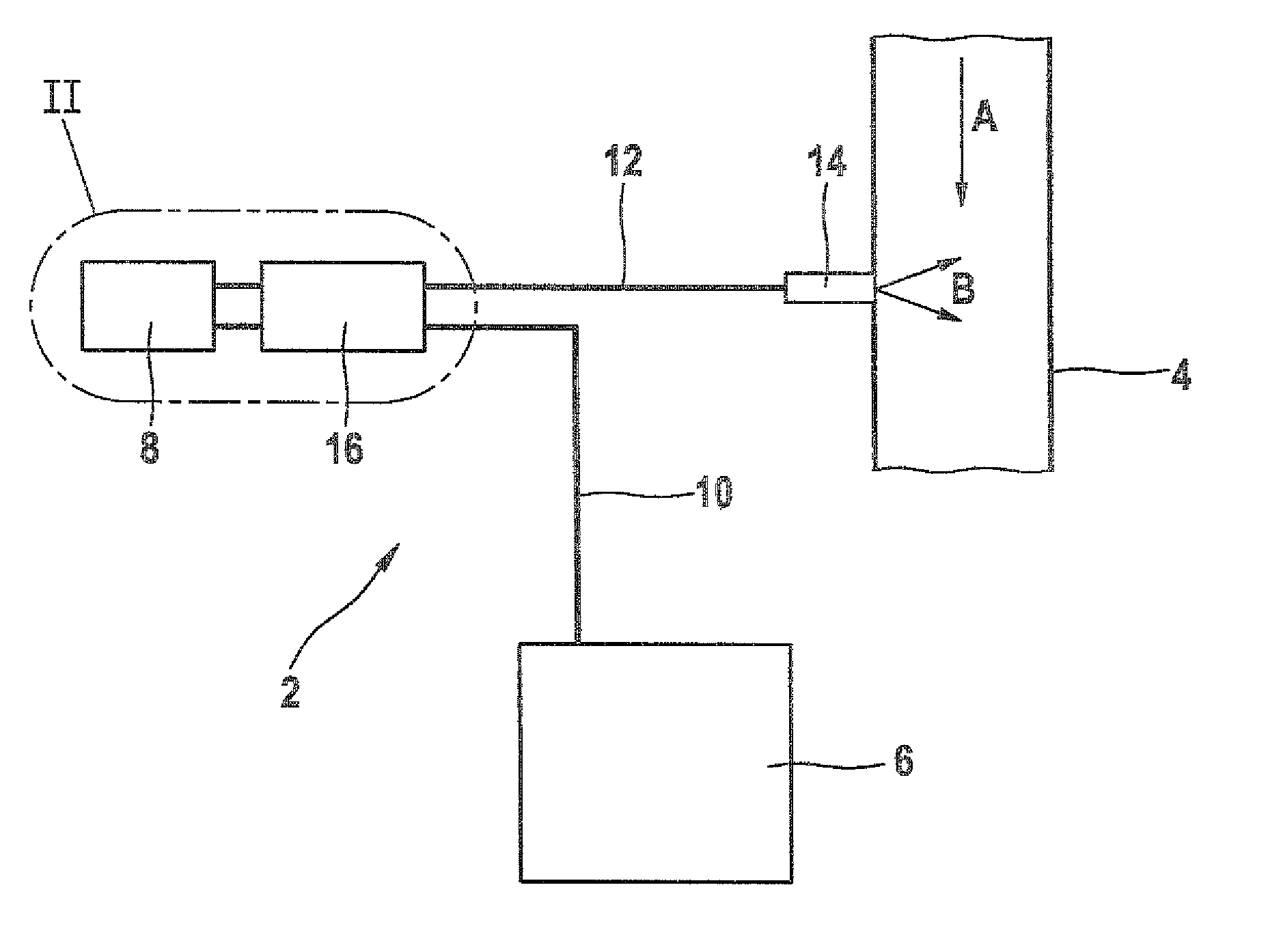
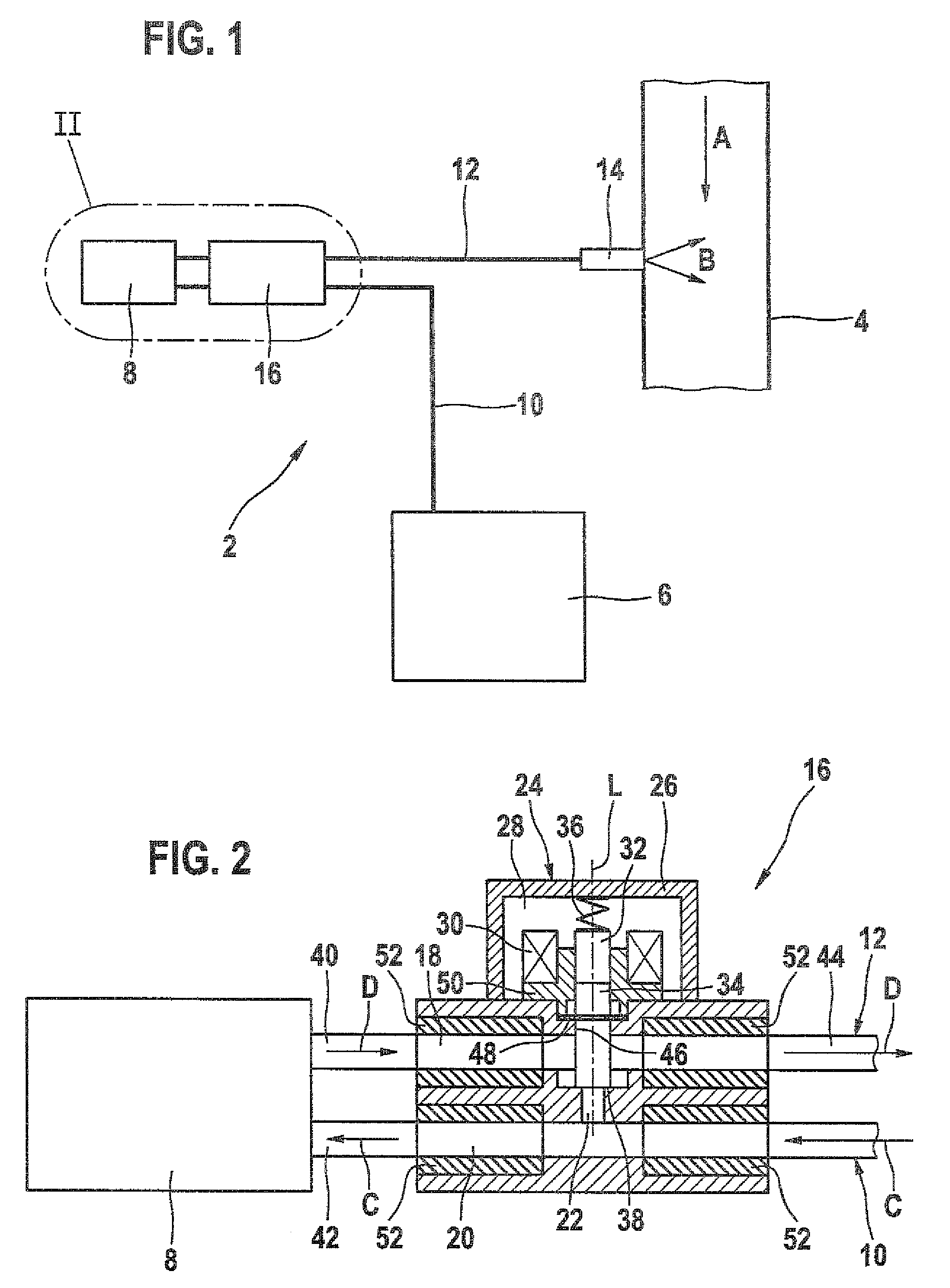
[0018]The device 2 shown in its entirety in FIG. 1 serves to deliver a reducing agent to an exhaust tube 4, through which exhaust gas from a diesel engine (not shown) flows in the direction of the arrow A. The delivered reducing agent is preferably a mixture of urea and water (AdBlue), but other reducing agents may also be used, in particular liquid reducing agents. The device 2 substantially comprises a tank 6 for the reducing agent, a conventional continuous-operation feed pump 8 for a liquid reducing agent, such as a mixture of urea and water, whose suction side communicates with the tank 6 through an intake line 10 and whose compression side communicates through a pressure line 12 with an injection nozzle 14 mounted on the exhaust tube 4, as well as a metering unit 16 for intermittently metering the reducing agent, pumped by the feed pump 8, through the injection nozzle 14 into the exhaust tube 4.

[0019]The injection nozzle 14, which for better mixing with the exhaust gas injects...


PUM

PropertyMeasurementUnit
pressureaaaaaaaaaa
forceaaaaaaaaaa
circumferenceaaaaaaaaaa

Abstract

The invention relates to a device for supplying a reducing agent into an exhaust system of an internal combustion engine. The device includes a delivery pump for delivering the reducing agent from a storage tank into an exhaust tube of the exhaust system. A metering device is provided between the delivery pump and the exhaust tube, which metering device supplies reducing agent, which is delivered continuously by the delivery pump, in an intermittent fashion into the exhaust tube.

Description

CROSS-REFERENCE TO RELATED APPLICATION[0001]This application is a 35 USC 371 application of PCT / EP 2007 / 052108 filed on Mar. 7, 2007.BACKGROUND OF THE INVENTION[0002]1. Field of the Invention[0003]The invention relates to a device for delivering a reducing agent, in particular a mixture of urea and water, to an exhaust system of an internal combustion engine.[0004]In selective catalytic reduction or SCR, to reduce the proportion of nitrogen oxide in the exhaust gas from diesel engines, a mixture of urea and water, commonly also called AdBlue, is delivered to the exhaust system. The urea in the injected solution is converted in the exhaust system into ammonia (NH3), which in a downstream SCR catalytic converter converts the nitrogen oxides (NOx) contained in the exhaust gas, forming molecular nitrogen (N2) and water (H2O). Since in this way the nitrogen oxides (NOx) can be removed almost completely from the exhaust gas, diesel engines can be operated with a relatively lean mixture, w...

Claims


Application Information

Patent Timeline
Patent Type & Authority Patents(United States)
IPC IPC(8): F01N3/00
CPCB01D53/90B01D53/9431F01N3/2066F01N3/208F01N9/00B01D2251/206F01N2610/02F01N2610/14F01N2610/1433F01N2610/146F01N2610/1473F01N2900/1808Y02T10/47Y02T10/24Y02T10/12Y02T10/40Y10T137/86027
Inventor BUERGLIN, MARKUSHEILIG, DIRK
Owner ROBERT BOSCH GMBH
Why Eureka
Try Eureka