Fire suppression system

a fire suppression system and sprinkler technology, applied in fire rescue, medical science, dental surgery, etc., can solve the problems of unfinished residential basements, thermoplastic sprinkler piping near the initial fire location, and the possibility of structural failure of fire suppression systems, so as to achieve more cost-effective effects

Inactive Publication Date: 2012-02-28
LUBRIZOL ADVANCED MATERIALS INC
View PDF16 Cites 17 Cited by
  • Summary
  • Abstract
  • Description
  • Claims
  • Application Information

AI Technical Summary

Benefits of technology

[0010]In an exemplary embodiment, a solenoid control valve operates to provide flow in a manner similar to an inspector's test connection. When the valve is activated, fluid flow is initiated so that instead of certain fluid conduits being filled with substantially stationary fire extinguishing fluid, the fire extinguishing fluid flows through the conduits, prior to opening of any sprinkler. In this way, if the incipient fire situation matures into a threshold thermal event, the flowing fluid (acting as a coolant) in the CPVC pipes will prolong the structural integrity of the pipes. If the incipient fire situation causes the temperature adjacent to a sprinkler to reach or exceed the limit for sprinkler activation, the thermally responsive element of the sprinkler will cause the sprinkler to deploy and distribute the fire suppression fluid from the sprinkler line to the fire.

Problems solved by technology

In the past when the principles of the exemplary embodiments have not been used in such testing, results have sometimes been unsatisfactory.
However, fire extinguishing fluid is discharged only within the covered zone of the open sprinkler heads, and not necessarily in the region of the fire.
The delay in activation of the local sprinkler may subject thermoplastic sprinkler piping near the initial fire location to the possibility of structural failure due to heat or direct flames.
Unfinished residential basements may also present challenges to fire suppression systems.
However, in unfinished residential basements, the “ceiling” may be absent, with the possibility of being added later.

Method used


Image

  • Fire suppression system
  • Fire suppression system
  • Fire suppression system

Examples


Embodiment Construction

[0023]The foregoing summary, as well as the following detailed description of exemplary embodiments, will be better understood when read in conjunction with the appended drawings. For the purpose of illustrating the exemplary embodiments, there is shown in the drawings certain exemplary systems. It should be understood, however, that these embodiments are merely exemplary and that the present invention is not limited to the systems, arrangements and instrumentalities shown or described herein.

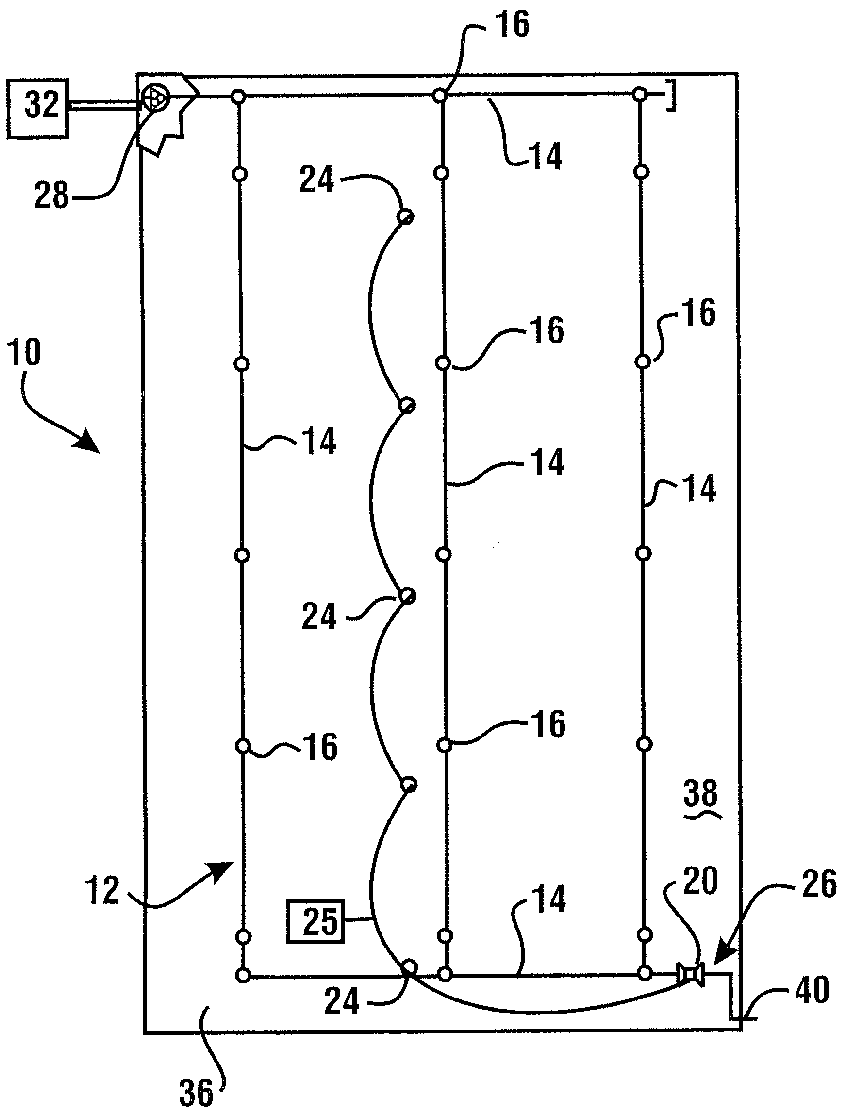
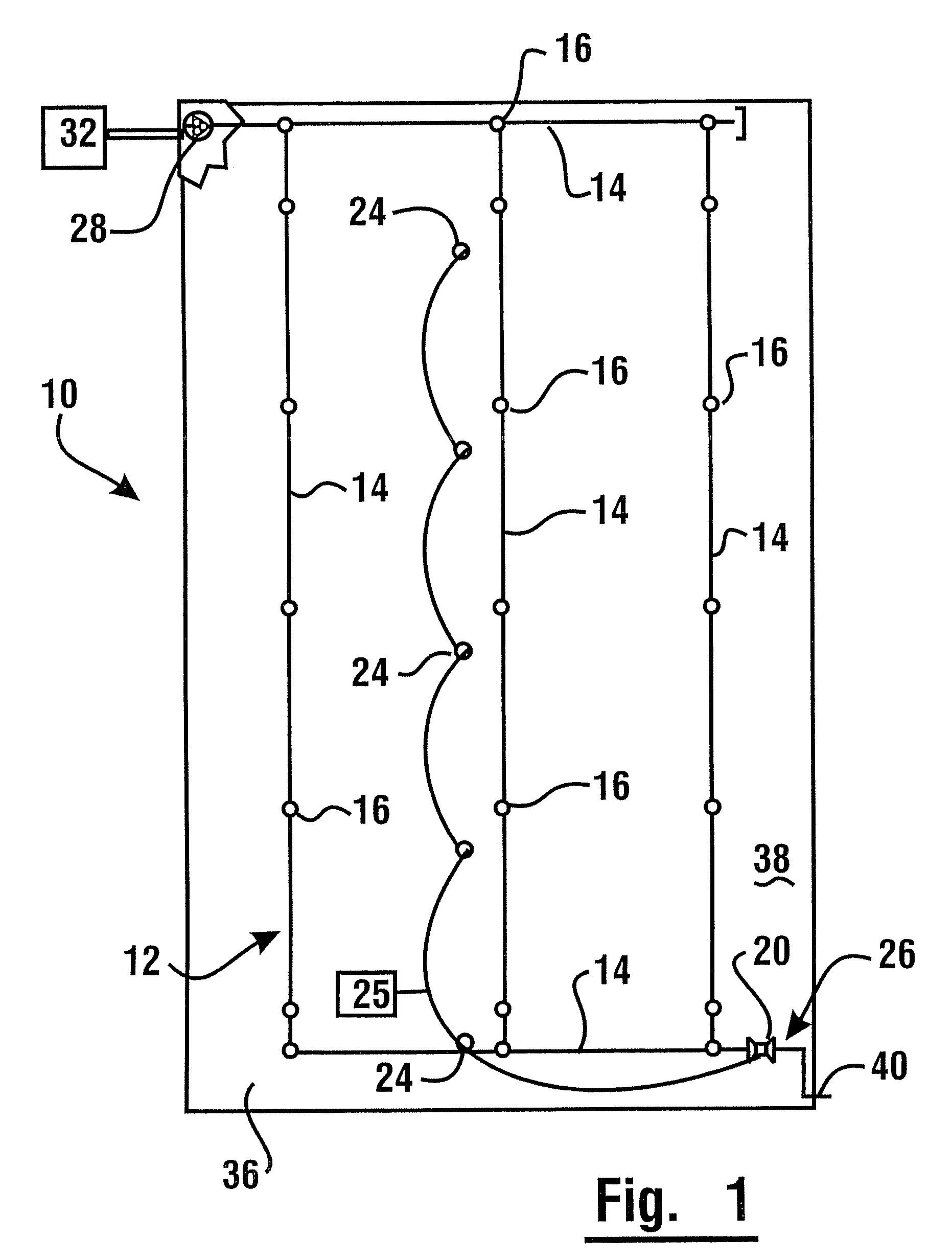
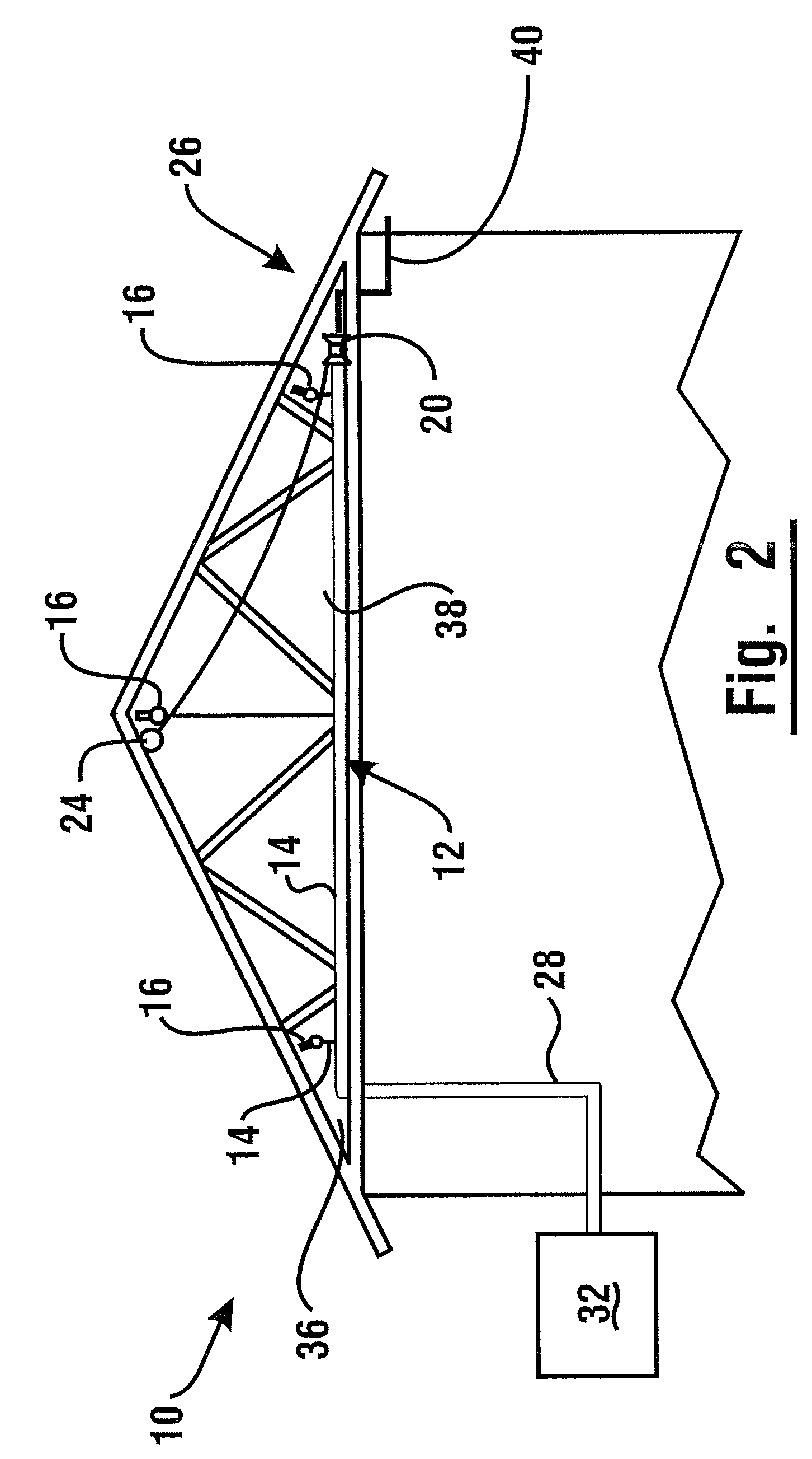
[0024]With respect to the Figures, in an exemplary embodiment, a fire suppression system 10 includes a sprinkler line 12 comprising a network of fluid conduits 14 which are formed of a thermoplastic material. In the exemplary embodiment, the fluid conduits are comprised of chlorinated polyvinyl chloride (CPVC). The fluid conduits (which are alternatively referred to herein as pipes) 14 are in flow communication with a plurality of fire sprinklers 16. The exemplary type of CPVC resin of which th...


PUM


Abstract

A sprinkler system comprises a network of CPVC conduits and a plurality of sprinklers. The system includes an electrically activated solenoid control valve to allow fluid to flow in the pipe network. One or more fire detectors operate independently of the condition of the sprinklers. Upon detection of an incipient fire situation, a fire detector sends an electrical signal to cause activation of the control valve. Upon activation of the control valve, fire suppression fluid is caused to flow through the conduits before the incipient fire situation matures into a sprinkler-triggering event. The cooling effect of fluid flowing through the conduit enables the conduit to resist structural failure prior to sprinkler deployment. The control valve may be disposed at a remote location in the sprinkler line and be operable as part of an inspector's test connection.

Description

CROSS REFERENCE TO RELATED APPLICATION[0001]This application claims the benefit of U.S. Provisional Application No. 60 / 784,565 filed Mar. 22, 2006, and the disclosure thereof is incorporated herein by reference.TECHNICAL FIELD[0002]The invention relates generally to fire sprinkler systems. More specifically, exemplary embodiments relate to a fire sprinkler system using CPVC pipes that may be installed in an attic or basement environment.BACKGROUND ART[0003]Sprinkler systems may be employed as a fire suppression measure. A sprinkler head may include a thermally responsive mechanism that operates so that when a fire causes a temperature limit to be reached, the sprinkler head will open and dispense fire extinguishing fluid. In general, fire suppression systems must meet stringent safety standards. Certain fire system standards dictate the placement and spacing of sprinkler heads.SUMMARY OF INVENTION[0004]The exemplary sprinkler systems discussed in more detail herein may be included i...

Claims


Application Information

Patent Timeline
Patent Type & Authority Patents(United States)
IPC IPC(8): A62C37/36
CPCA62C35/68A62C35/58A62C37/50A62C37/44A62C35/62
Inventor JOHNSON, GARY L.
Owner LUBRIZOL ADVANCED MATERIALS INC
Why Eureka
Try Eureka