Diaphragm pump

a diaphragm pump and diaphragm technology, which is applied in the direction of mechanical equipment, engine working fluid, liquid fuel engine, etc., can solve the problems of large size, complex construction, and high investment required, and achieve the effect of reducing susceptibility, increasing the service life of the diaphragm, and increasing the elastic deformation

Inactive Publication Date: 2012-02-28
J WAGNER GMBH
View PDF20 Cites 21 Cited by
  • Summary
  • Abstract
  • Description
  • Claims
  • Application Information

AI Technical Summary

Benefits of technology

[0009]In this case, the reaction spaces holding the hydraulic linkage assigned to the diaphragms and the connection lines connected to the reaction spaces are completely filled with a hydraulic medium and are configured so they are hermetically sealed, the hydraulic fluid forming the hydraulic linkage acted on by atmospheric pressure or a low pressure of up to 0.09 MPa, and the line connecting the two reaction spaces of the diaphragms is closed or sealed by a plug so it is fluid-tight. In this way, it is assured that the diaphragms are fixed in the specified position.
[0010]In order to seal the reaction spaces internally, it is advantageous to provide each with a bellows clamped at one end against the cylinder and at the other end against the piston rods. Each of the spaces enclosed by the bellows should always be connected to the immediately adjacent pressure space of the adjusting piston by means of one or more openings worked into the cylinder.
[0011]If a diaphragm pump is configured in accordance with the present invention, this guarantees that both diaphragms will always remain in approximately the specified installation position and will not fold over at the transition from a suction stroke to a pressure stroke. The sides of the diaphragms facing towards the cylinder are always in contact with the hydraulic linkage and this linkage does not allow the diaphragms to lift off, so therefore they are only exposed to tensile stress during adjustment movements and are therefore not subjected to alternating loads. The service life of the diaphragms can therefore be increased significantly without the need to design or configure them in any special way.
[0012]The structural complexity needed to reduce the susceptibility to malfunctions of diaphragm pumps of this kind due to diaphragm damage is small because it is merely necessary to select a certain convex or concave installation position for the diaphragms in relation to the cylinder and, in addition, they are rigidly connected together to a certain extent via the hydraulic linkage. The provided hydraulic linkage against which the diaphragms make contact over a wide area is particularly well suited to this purpose without the need for a mechanical linkage. The hydraulic linkage follows the corresponding adjustment movements of the diaphragms because the reaction spaces are connected together, meaning that the diaphragms cannot fold over and are only subjected to minor flexing movements. Diaphragms that are only subjected to tensile forces can therefore be designed to allow greater elastic deformation.
[0013]A further advantage is that no spatial expansions occur in the pumping spaces of the diaphragm pump following a change in direction, i.e. after changing over from a suction stroke to a pressure stroke or vice versa, which would, amongst other effects, briefly interrupt the pumping flow. As a result, no pulsation effects can be detected in the pumping line, which means that the operating behavior of the diaphragm pump configured in accordance with the present invention is improved.

Problems solved by technology

In this case, pressurized medium is supplied in a controlled fashion to the pressure spaces synchronously to the adjustment movements of the drive piston of a pneumatic motor that is mechanically connected to the diaphragms, with the effect that although a pressure ratio is achieved, the complexity of the construction and the level of the investment required are both considerable.
This is because a separate control device is provided in between the pneumatic motor and one of the diaphragms, and this control device is susceptible to defects and large in size.
However, the principal disadvantage is that each of the diaphragms folds over during the transition from a suction stroke to a pressure stroke and their flexing zones are highly stressed by the alternating tensile and compression loads.
This leads to damage to the diaphragms after only a relatively short operating time, meaning that the diaphragms have to be renewed and interruptions in operation have to be accepted in such cases.
Furthermore, the folding over of the diaphragms has an unfavorable effect on the pumping behavior of the diaphragm pump because changes in volume in the pumping spaces are unavoidable and the pumping flow pulsates as a result.

Method used


Image

  • Diaphragm pump
  • Diaphragm pump
  • Diaphragm pump

Examples


Embodiment Construction

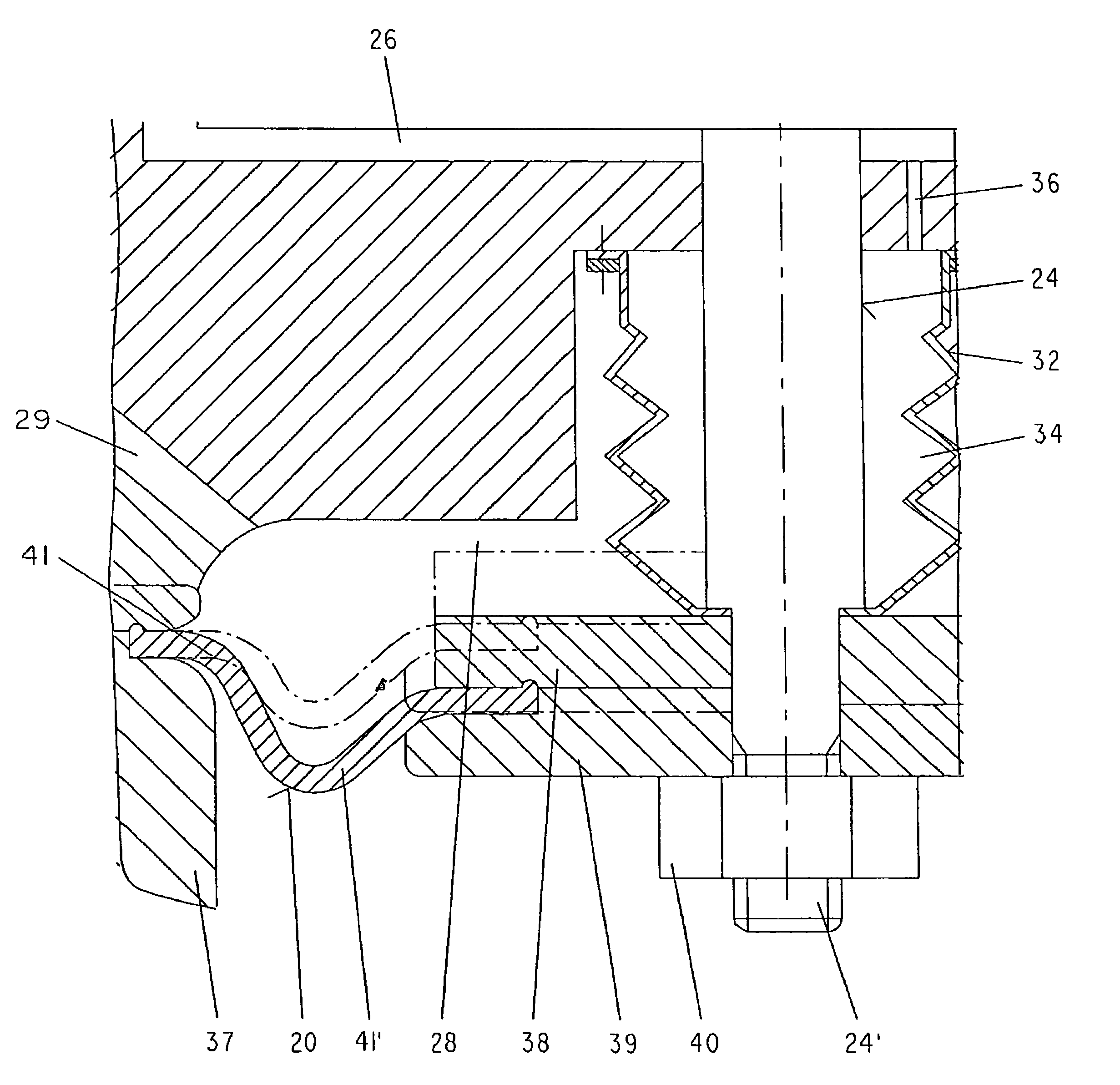
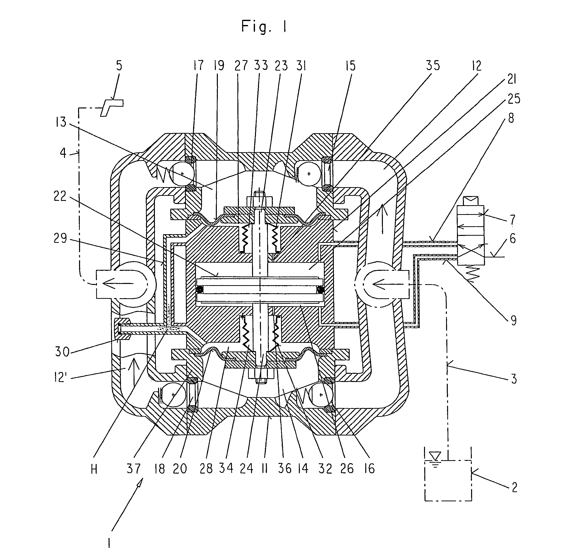
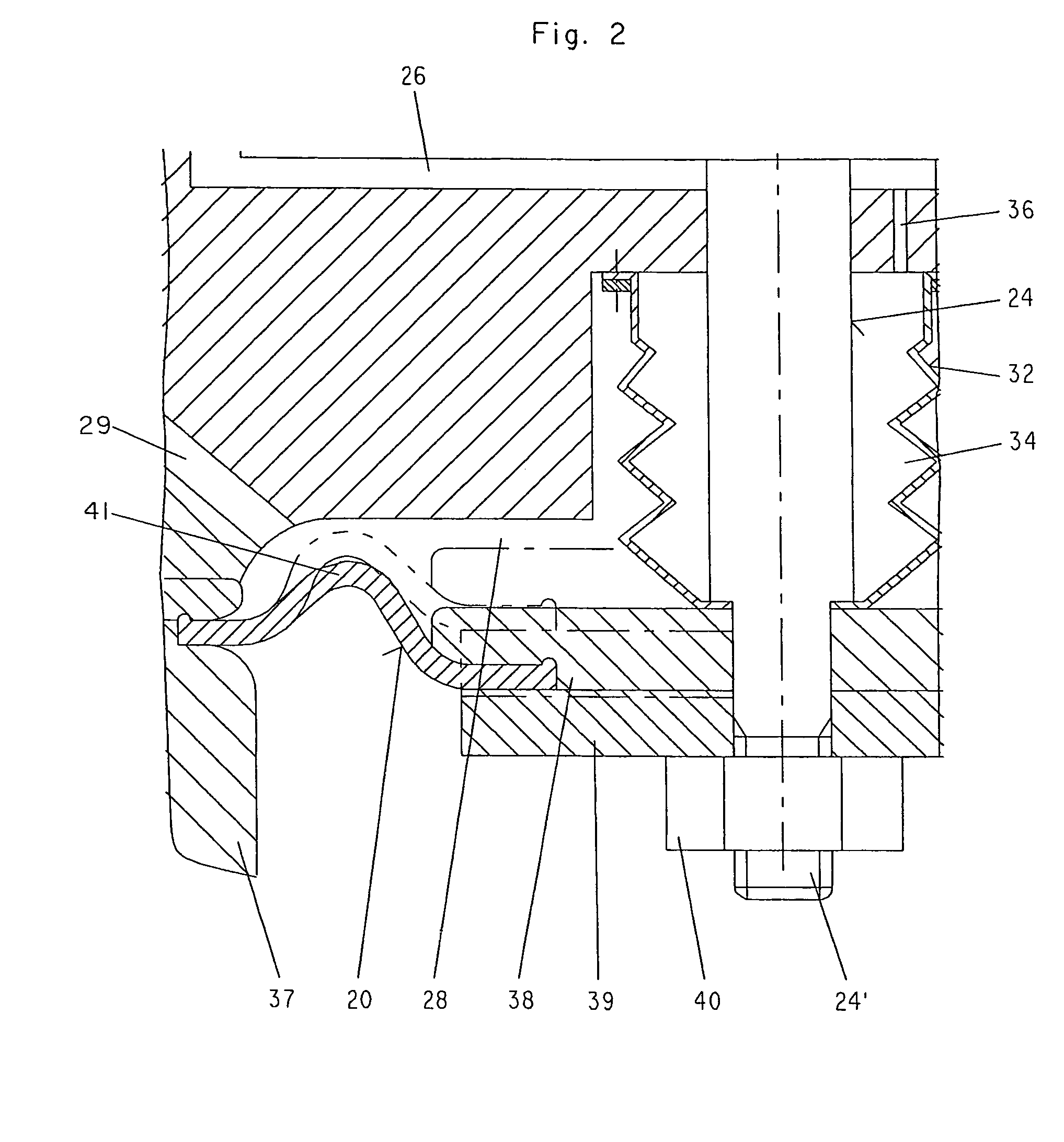
[0018]The diaphragm pump shown in FIG. 1 and identified with 1 is used for pumping a liquid, for example a paint to be processed, out of a reservoir container 2 to a spray gun 5 and consists in principle of two diaphragms 19 and 20 arranged in a housing 11 being in a driven connection with an adjusting piston 22 upon which a pressurized medium can act alternately. A suction line 3 connects the diaphragm pump 1 to the reservoir container 2, while a pressure line 4 connects the diaphragm pump 1 to the spray gun 5.

[0019]In the embodiment illustrated, the adjusting piston 22 is arranged in a cylinder 21 installed between the two diaphragms 19 and 20 in a housing 11. Pressurized medium is supplied alternately to the pressure spaces 25 and 26 of the adjusting piston 22 in order to actuate the diaphragms, the pressurized medium being taken from a pressure line 6, and with a 4 / 2-way valve for inputting the pressurized medium into downstream pressure lines 8 or 9 that are connected to the pr...


PUM


Abstract

In a diaphragm pump with two diaphragms disposed in a pump housing and actuated by an adjusting piston which can be acted on alternately and which is arranged in between the diaphragms, the diaphragms are fixed with curvatures facing one another, or a curvature facing away from one another, and two reaction spaces are formed between the diaphragms and a cylinder, the reaction spaces accommodating the adjusting piston and being filled with a hydraulic medium and connected together in a constrained arrangement by means of hydraulic linkage lines. Both diaphragms remain in position and do not fold over during a transition from a suction stroke to a pressure stroke, because the diaphragms are continuously in contact with the hydraulic lines and are thereby fixed in place, so that the diaphragms are not subjected to alternating loadings.

Description

REFERENCE TO PRIOR PENDING PATENT APPLICATION[0001]This patent application claims the benefit of pending prior European Patent Application No. 05008040.7, filed Apr. 12, 2005 by Karsten Jüterbock et al. for DIAPHRAGM PUMP, which patent application is hereby incorporated herein by reference.BACKGROUND OF THE INVENTION[0002]1. Field of the Invention[0003]The present invention relates to a diaphragm pump with two diaphragms disposed in a pump housing which act on a fluid medium to be pumped, e.g. a paint, which diaphragms can be actuated by means of an adjusting piston arranged in between the diaphragms upon both sides of which a pressurized medium can act alternately and which diaphragms are supported in the terminal areas of two piston rods that are firmly connected to the adjusting piston.[0004]2. Description of the Prior Art:[0005]A diaphragm pump of this type is disclosed in DE 195 35 745 C1. In this embodiment, a further pressure space is assigned to each of the two diaphragms an...

Claims


Application Information

Patent Timeline
Patent Type & Authority Patents(United States)
IPC IPC(8): F04B45/053F04B43/06
CPCF04B43/0736F04B9/113F04B43/025F04B43/073F04B53/16F04B53/14F04B53/10F04B53/02F05B2210/11
Inventor JUTERBOCK, KARSTENBASSO, ANGELO
Owner J WAGNER GMBH
Why Eureka
Try Eureka