Heat-assisted magnetic recording head including plasmon generator

a technology of magnetic recording head and plasmon generator, which is applied in the field of heat-assisted magnetic recording head, can solve the problems of increasing the coercivity of the magnetic recording medium, reducing the thermal stability of the magnetization of the magnetic fine particles, and difficult to perform data writing with the existing magnetic recording head

Active Publication Date: 2012-02-28
TDK CORPARATION
View PDF12 Cites 5 Cited by
  • Summary
  • Abstract
  • Description
  • Claims
  • Application Information

AI Technical Summary

Benefits of technology

[0013]It is an object of the present invention to provide a heat-assisted magnetic recording head that allows efficient use of light propagated through a waveguide's core and allows generation of near-field light having a small spot diameter from a plasmon generator, and to provide a head gimbal assembly and a magnetic recording device that each include such a heat-assisted magnetic recording head.
[0021]In the heat-assisted magnetic recording head, the head gimbal assembly, and the magnetic recording device of the present invention, a surface plasmon is excited on the propagation edge of the plasmon generator through coupling with the evanescent light generated from the evanescent light generating surface of the core of the waveguide. The surface plasmon is propagated along the propagation edge to the near-field light generating part. The near-field light generating part generates near-field light based on the surface plasmon. In the present invention, the plasmon generator includes the shape changing portion in which the radius of curvature of the propagation edge in the cross section parallel to the medium facing surface continuously decreases with decreasing distance to the medium facing surface. The present invention thus makes it possible to use the light propagated through the core of the waveguide with high efficiency and to generate near-field light having a small spot diameter from the plasmon generator.

Problems solved by technology

However, making the magnetic fine particles smaller causes the problem that the thermal stability of magnetization of the magnetic fine particles decreases with decreasing volume of the magnetic fine particles.
However, increasing the anisotropic energy of the magnetic fine particles leads to an increase in coercivity of the magnetic recording medium, and this makes it difficult to perform data writing with existing magnetic heads.
However, the plasmon antenna which generates near-field light by direct irradiation with light is known to exhibit very low efficiency of transformation of the applied light into near-field light.
This causes an end of the read head located in the medium facing surface to get farther from the magnetic recording medium, thereby causing the problem that a servo signal cannot be read during write operations.
Reducing the radius of curvature of the edge part in cross section parallel to the medium facing surface, however, causes the problem of reducing surface plasmons to be excited on the edge part, thereby causing a drop in the use efficiency of the light that is propagated through the core.

Method used


Image

  • Heat-assisted magnetic recording head including plasmon generator
  • Heat-assisted magnetic recording head including plasmon generator
  • Heat-assisted magnetic recording head including plasmon generator

Examples


first embodiment

[0061]Preferred embodiments of the present invention will now be described in detail with reference to the drawings. First, reference is made to FIG. 6 to describe a magnetic disk drive as a magnetic recording device according to a first embodiment of the invention. As shown in FIG. 6, the magnetic disk drive includes a plurality of magnetic disks 201 as a plurality of magnetic recording media, and a spindle motor 202 for rotating the plurality of magnetic disks 201. The magnetic disks 201 of the present embodiment are for use in perpendicular magnetic recording. Each magnetic disk 201 has such a structure that a soft magnetic backing layer, a middle layer, and a magnetic recording layer (perpendicular magnetization layer) are stacked in this order on a disk substrate.

[0062]The magnetic disk drive further includes an assembly carriage device 210 having a plurality of driving arms 211, and a plurality of head gimbal assemblies 212 attached to respective distal ends of the driving arm...

second embodiment

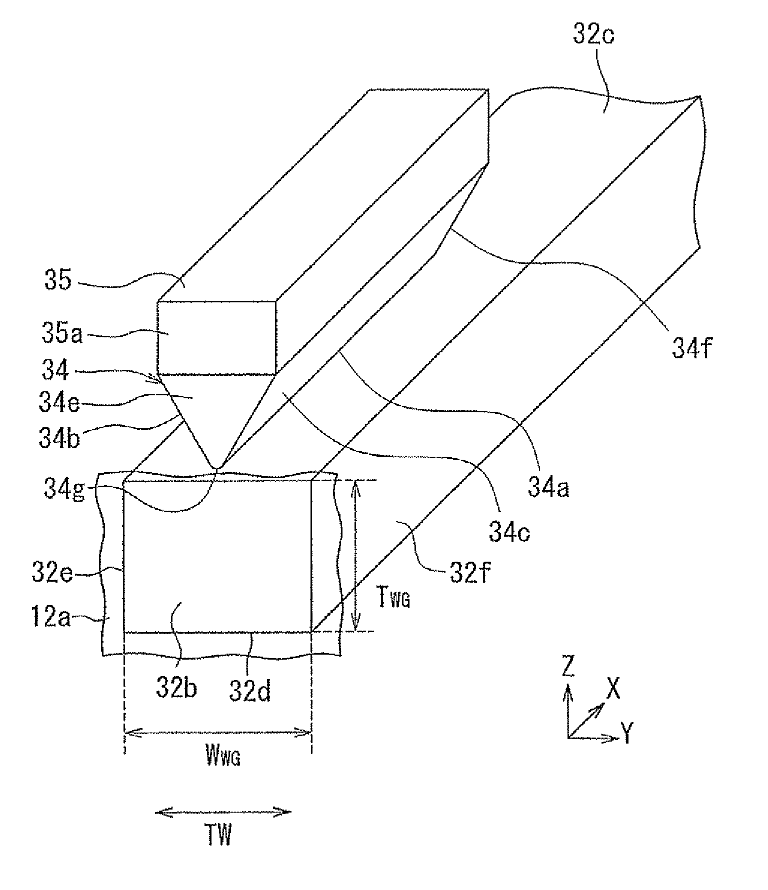
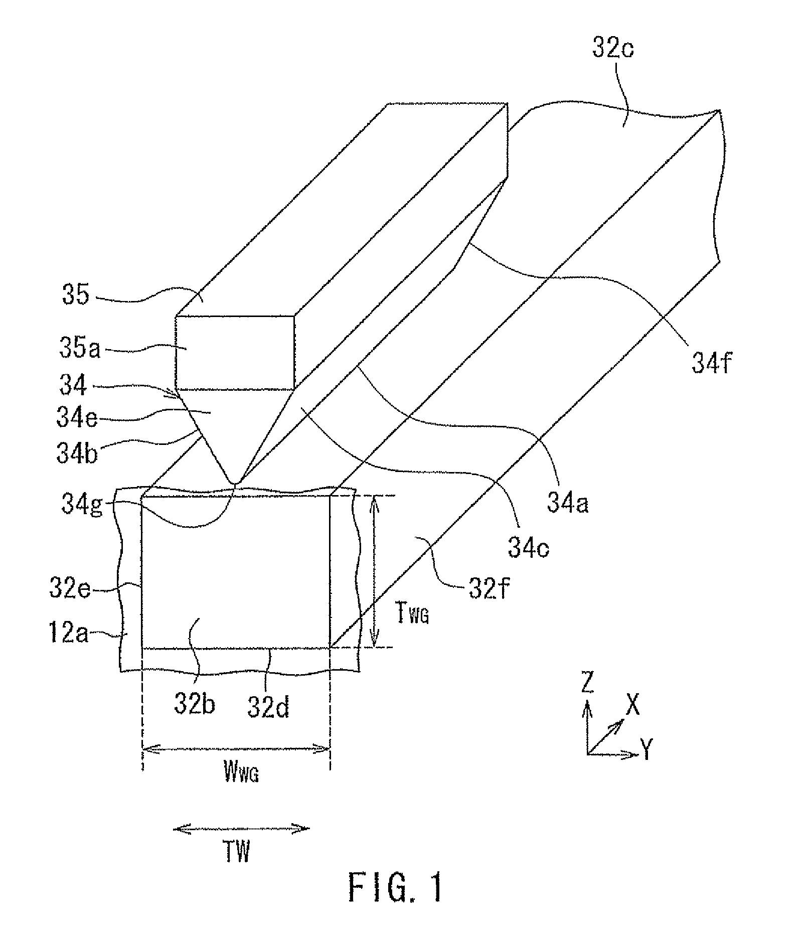
[0144]A second embodiment of the present invention will now be described with reference to FIG. 22 to FIG. 25. FIG. 22 is a perspective view showing the core of the waveguide, the plasmon generator, and the magnetic pole of the heat-assisted magnetic recording head according to the present embodiment. FIG. 23 is an exploded perspective view of the plasmon generator and the magnetic pole shown in FIG. 22. FIG. 24 is a front view showing the core, the plasmon generator, and a first layer of the magnetic pole shown in FIG. 22. FIG. 25 is a cross-sectional view showing respective cross sections of the core, the plasmon generator, and the first layer of the magnetic pole shown in FIG. 22 parallel to the medium facing surface. FIG. 26 is a cross-sectional view showing the core of the waveguide, the plasmon generator, and the magnetic pole of the heat-assisted magnetic recording head according to the present embodiment. The heat-assisted magnetic recording head according to the present emb...

third embodiment

[0167]A third embodiment of the present invention will now be described with reference to FIG. 28 to FIG. 30. FIG. 28 is a perspective view showing the core of the waveguide, the plasmon generator, and the magnetic pole of the present embodiment. FIG. 29 is an exploded perspective view of the plasmon generator and the magnetic pole shown in FIG. 28. FIG. 30 is a perspective view of the core and the plasmon generator shown in FIG. 28. The heat-assisted magnetic recording head according to the present embodiment has a plasmon generator 84 instead of the plasmon generator 34 of the first embodiment. In the present embodiment, as in the second embodiment, the magnetic pole 35 includes a first layer 351 and a second layer 352, the second layer 352 lying on the first layer 351.

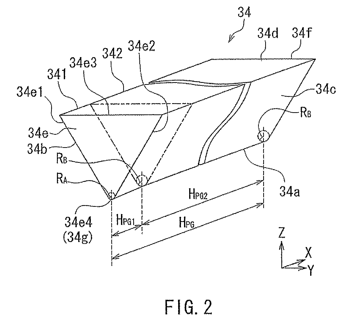
[0168]As shown in FIG. 30, the plasmon generator 84 has a V-shaped portion 841 that has an end face located in the medium facing surface 12a. The V-shaped portion 841 extends in the direction perpendicular to the me...


PUM

PropertyMeasurementUnit
wavelengthaaaaaaaaaa
emittable wavelength rangeaaaaaaaaaa
thickness TLAaaaaaaaaaa

Abstract

A plasmon generator has an outer surface including a propagation edge, and has a near-field light generating part lying at an end of the propagation edge and located in a medium facing surface. The propagation edge faces an evanescent light generating surface of a waveguide's core with a predetermined distance therebetween and extends in a direction perpendicular to the medium facing surface. The propagation edge is arc-shaped in a cross section parallel to the medium facing surface. The plasmon generator includes a shape changing portion in which a radius of curvature of the propagation edge in the cross section parallel to the medium facing surface continuously decreases with decreasing distance to the medium facing surface.

Description

BACKGROUND OF THE INVENTION[0001]1. Field of the Invention[0002]The present invention relates to a heat-assisted magnetic recording head including a plasmon generator for use in heat-assisted magnetic recording where a magnetic recording medium is irradiated with near-field light to lower the coercivity of the magnetic recording medium for data writing.[0003]2. Description of the Related Art[0004]Recently, magnetic recording devices such as magnetic disk drives have been improved in recording density, and thin-film magnetic heads and magnetic recording media of improved performance have been demanded accordingly. Among the thin-film magnetic heads, a composite thin-film magnetic head has been used widely. The composite thin-film magnetic head has such a structure that a read head including a magnetoresistive element (hereinafter, also referred to as MR element) intended for reading and a write head including an induction-type electromagnetic transducer intended for writing are stack...

Claims


Application Information

Patent Timeline
Patent Type & Authority Patents(United States)
IPC IPC(8): G11B11/00
CPCG11B5/314G11B5/6088G11B5/3163G11B2005/001G11B2005/0021
Inventor TANAKA, KOSUKEMIYAUCHI, DAISUKEAOKI, SUSUMUROPPONGI, TETSUYACHOU, TSUTOMUHARA, SHINJIKOMURA, EIJI
Owner TDK CORPARATION
Why Eureka
Try Eureka