
Lifting-based view compensated compression and remote visualization of volume rendered images

a compression and image technology, applied in the field of image visualization, can solve the problems of limited quality and frame rate in the client side rendering system, image rendering can be a computationally intensive process,

Active Publication Date: 2012-02-28
SIEMENS HEALTHCARE GMBH +1
View PDF3 Cites 189 Cited by
  • Summary
  • Abstract
  • Description
  • Claims
  • Application Information

AI Technical Summary

Benefits of technology

This approach enhances the efficiency of image compression and remote visualization, allowing for higher quality and frame rate rendering by optimizing the compression of rendered images, thereby improving the client-side rendering experience.

Problems solved by technology

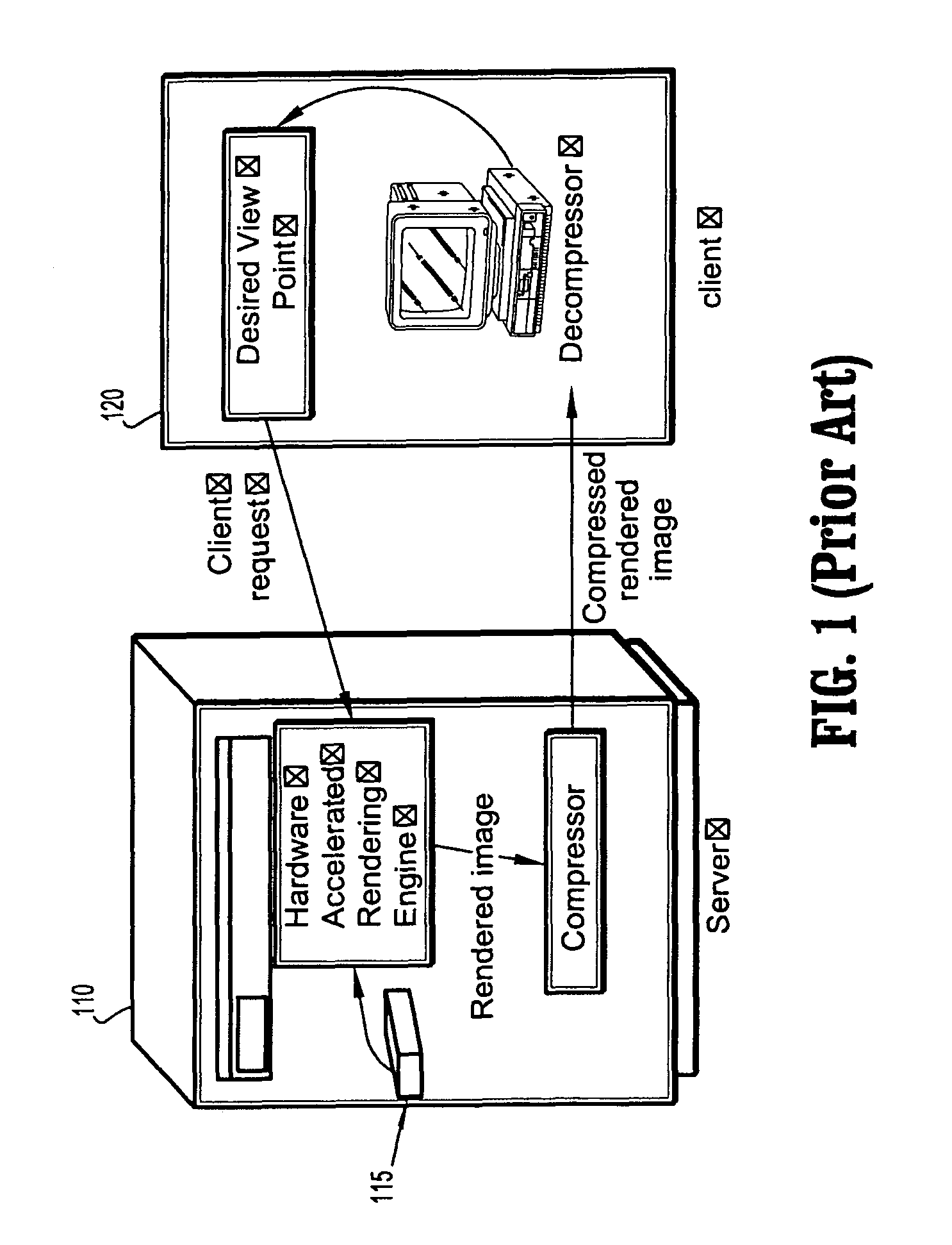
However, image rendering can be a computationally intensive process, often requiring hardware acceleration to achieve a real time viewing experience.
Thus, it is likely that the quality and frame rate would be limited in a client side rendering system.

Method used


Image

  • Lifting-based view compensated compression and remote visualization of volume rendered images
  • Lifting-based view compensated compression and remote visualization of volume rendered images
  • Lifting-based view compensated compression and remote visualization of volume rendered images

Examples


Embodiment Construction

[0020]In general, exemplary methods and systems for compressing and remotely visualizing volume rendered images will now be discussed in further detail with reference to FIGS. 1-7.

[0021]It is to be understood that the systems and methods described herein may be implemented in various forms of hardware, software, firmware, special purpose processors, or a combination thereof. In particular, at least a portion of the present invention is preferably implemented as an application comprising program instructions that are tangibly embodied on one or more program storage devices (e.g., hard disk, magnetic floppy disk, RAM, ROM, CD ROM, etc.) and executable by any device or machine comprising suitable architecture, such as a general purpose digital computer having a processor, memory, and input / output interfaces. It is to be further understood that, because some of the constituent system components and process steps depicted in the accompanying figures are preferably implemented in software...


PUM


Abstract

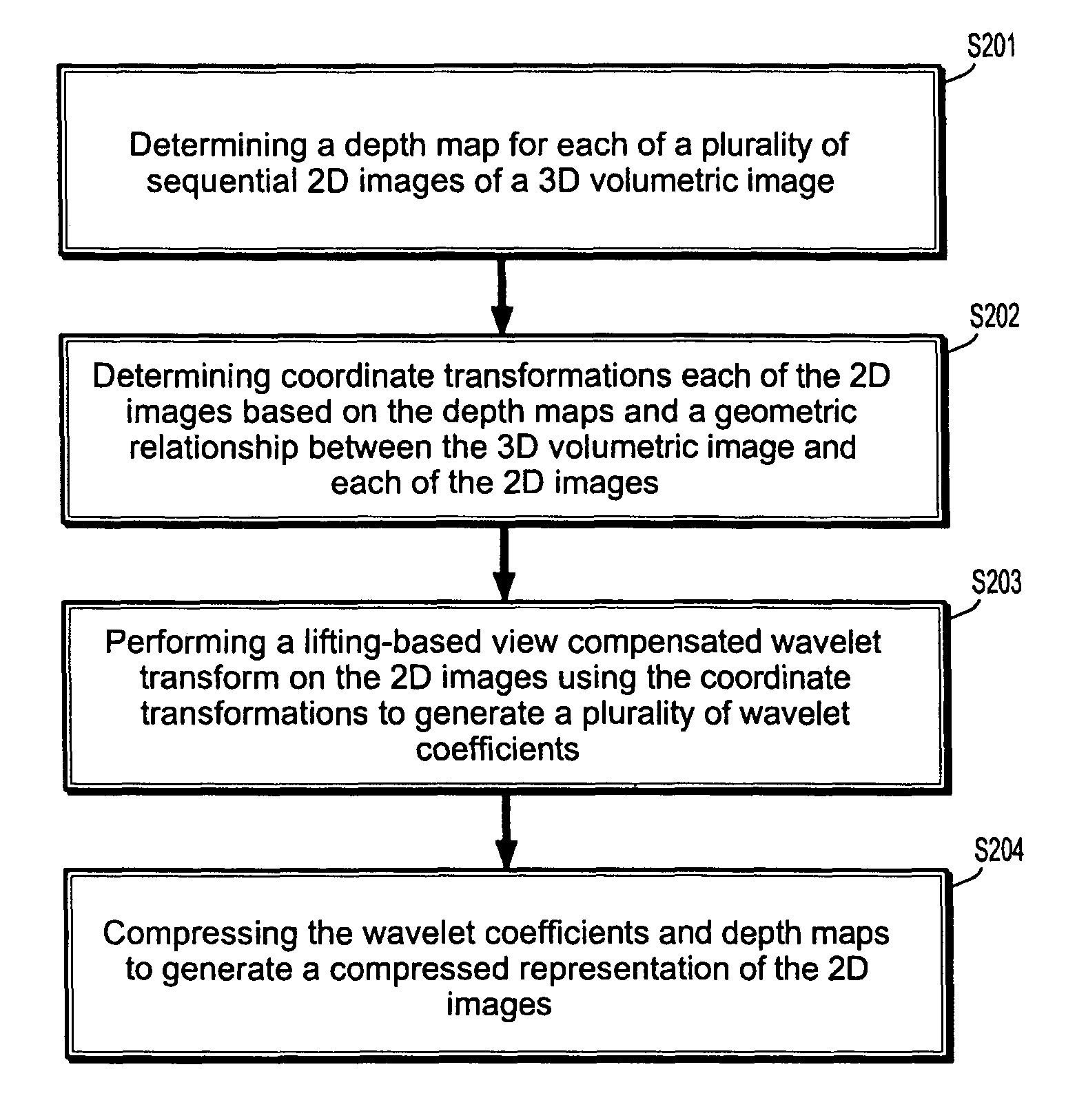
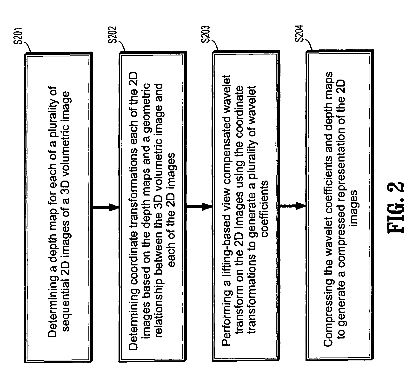
A method for compressing 2D images includes determining a depth map for each of a plurality of sequential 2D images of a 3D volumetric image, determining coordinate transformations the 2D images based on the depth maps and a geometric relationship between the 3D volumetric image and each of the 2D image, performing a lifting-based view compensated wavelet transform on the 2D images using the coordinate transformations to generate a plurality of wavelet coefficients and compressing the wavelet coefficients and depth maps to generate a compressed representation of the 2D images.

Description

CROSS-REFERENCE TO RELATED APPLICATIONS[0001]This application claims priority to U.S. Provisional Application No. 61 / 003,619, filed on Nov. 19, 2007, the disclosure of which is incorporated by reference herein.BACKGROUND OF THE INVENTION[0002]1. Technical Field[0003]The present disclosure relates generally to the field of image visualization, and more specifically to methods and systems for compressing and remotely visualizing volume rendered images.[0004]2. Discussion of Related Art[0005]With tremendous advances in volume imaging modalities, remote visualization of volumetric images has gained importance in many applications such as medical imaging, nondestructive testing and computational fluid dynamics.[0006]In one method of remote visualization, volumetric data is transmitted from a server to a client and one or more images are rendered on the client from the volumetric data for local display. However, image rendering can be a computationally intensive process, often requiring h...

Claims


Application Information

Patent Timeline
Patent Type & Authority Patents(United States)
IPC IPC(8): G06K9/36
CPCH04N19/647G06T15/08
Inventor MARCELLIN, MICHAEL W.BILGIN, ALILALGUDI, HARIHARAN G.NADAR, MARIAPPAN S.
Owner SIEMENS HEALTHCARE GMBH
Learn More