Robotic floor cleaning with sterile, disposable cartridges

a technology of disposable cartridges and robots, applied in the direction of carpet cleaners, coupling device connections, instruments, etc., can solve the problems of contaminated surfaces, disposable cleaning assemblies, and inability of devices to provide sterile cleaning of surfaces, etc., to reduce the “turnover time

Inactive Publication Date: 2012-03-06
OPTIMUS LICENSING AG
View PDF64 Cites 48 Cited by
  • Summary
  • Abstract
  • Description
  • Claims
  • Application Information

AI Technical Summary

Benefits of technology

[0017]An automated (robotic) floor-cleaner, such as the commercially available SCOOBA® or FLOOR GENIE™, is adapted to allow sterile cleaning of sensitive environments, such as a hospital operating room. In particular, the floor-cleaner chassis is redesigned to be mounted on a deck containing cleaning devices that contact the floor. The cleaning devices mounted on the deck, which can comprise such cleaning devices as vacuum heads, brushes, cleaning fluid sprays, and conceivably sanitizing devices such as a UV germicidal light, are provided pre-sterilized. As such, the adapted floor-cleaner chassis allows the deck to be mounted to the bottom of the chassis; the floor cleaner is then used to clean a floor, after which, the deck is removed from the chassis and disposed. The robotic-floor cleaner and sterilization system cleans floors between or even during cases. The system's disposable, sterile cleaning-cassettes ensure a sterile environment. Further, the robotic floor cleaner reduces the “turnover time” required between cases, as it operates simultaneously while staff prepare the room for the next case.
[0028]Therefore, one object of the present invention is to provide a sterile cleaning device that is operable without human intervention to clean designated areas.

Problems solved by technology

Nonetheless, these devices are not adapted to provide cleaning of surfaces using sterile, disposable cleaning assemblies.
In other words, after said cleaning devices clean a dirty floor, the incorporated brushes and surfaces in contact with said floor become contaminated.

Method used


Image

  • Robotic floor cleaning with sterile, disposable cartridges
  • Robotic floor cleaning with sterile, disposable cartridges
  • Robotic floor cleaning with sterile, disposable cartridges

Examples


Embodiment Construction

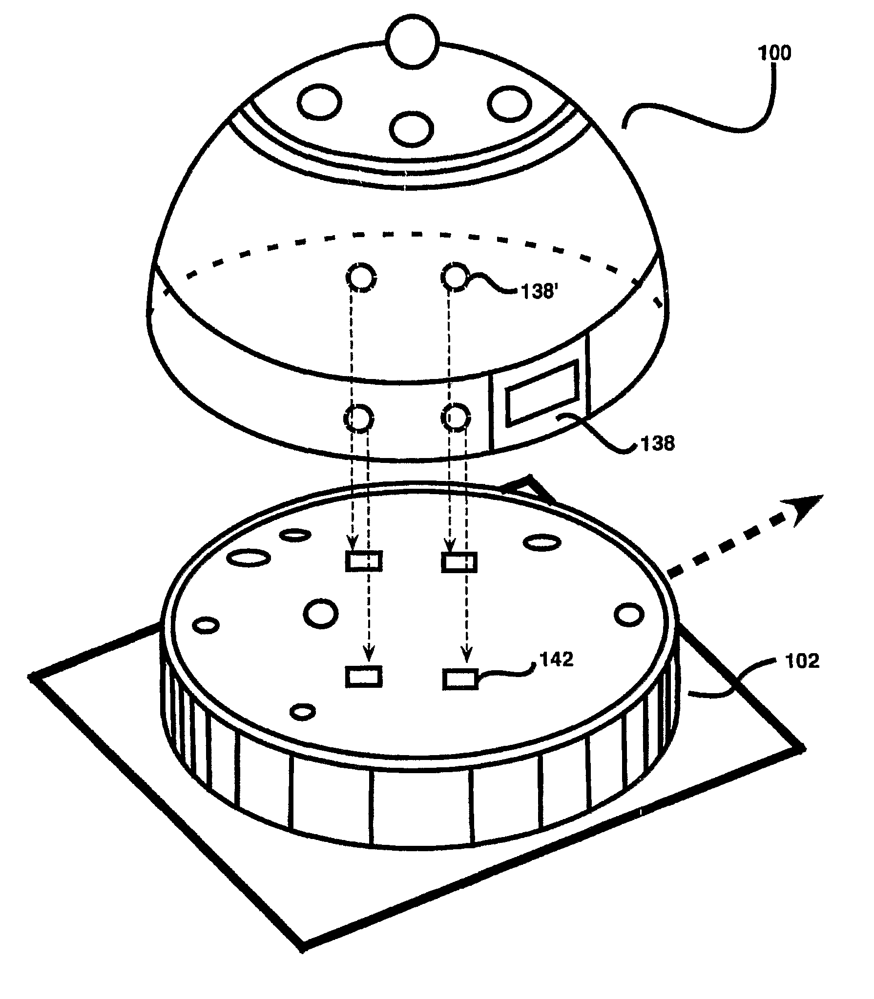
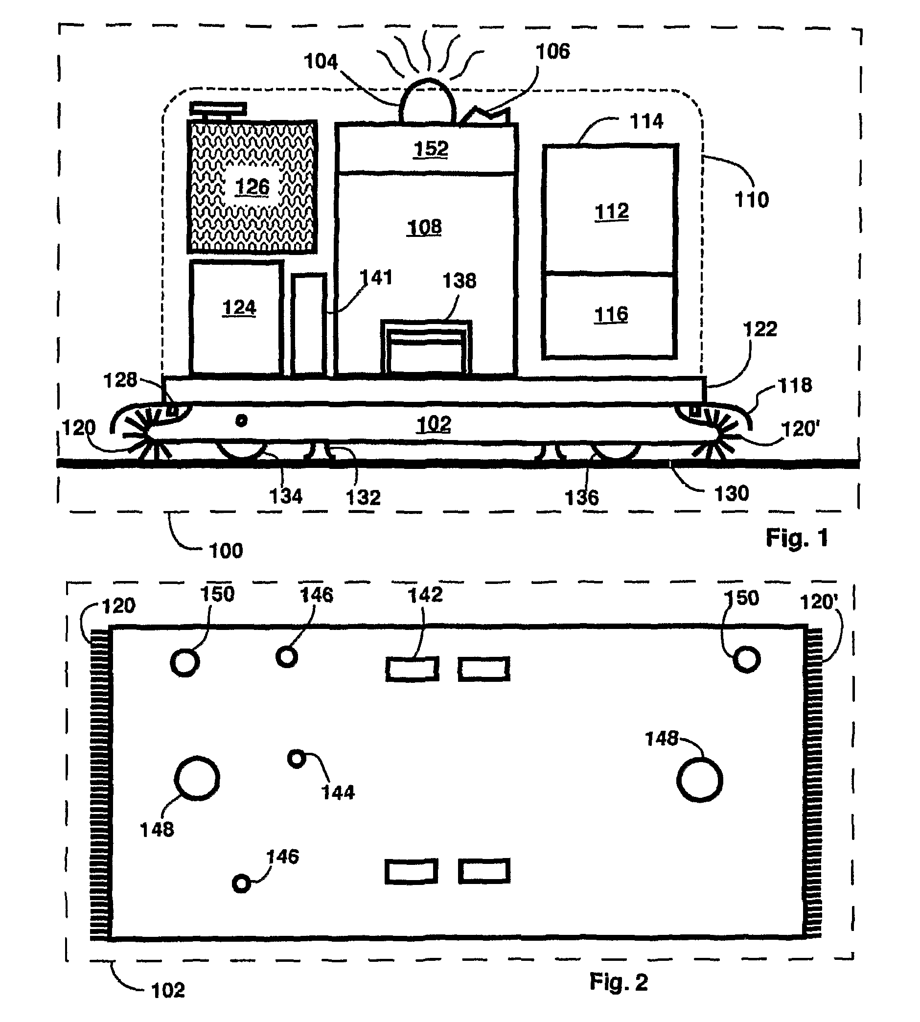
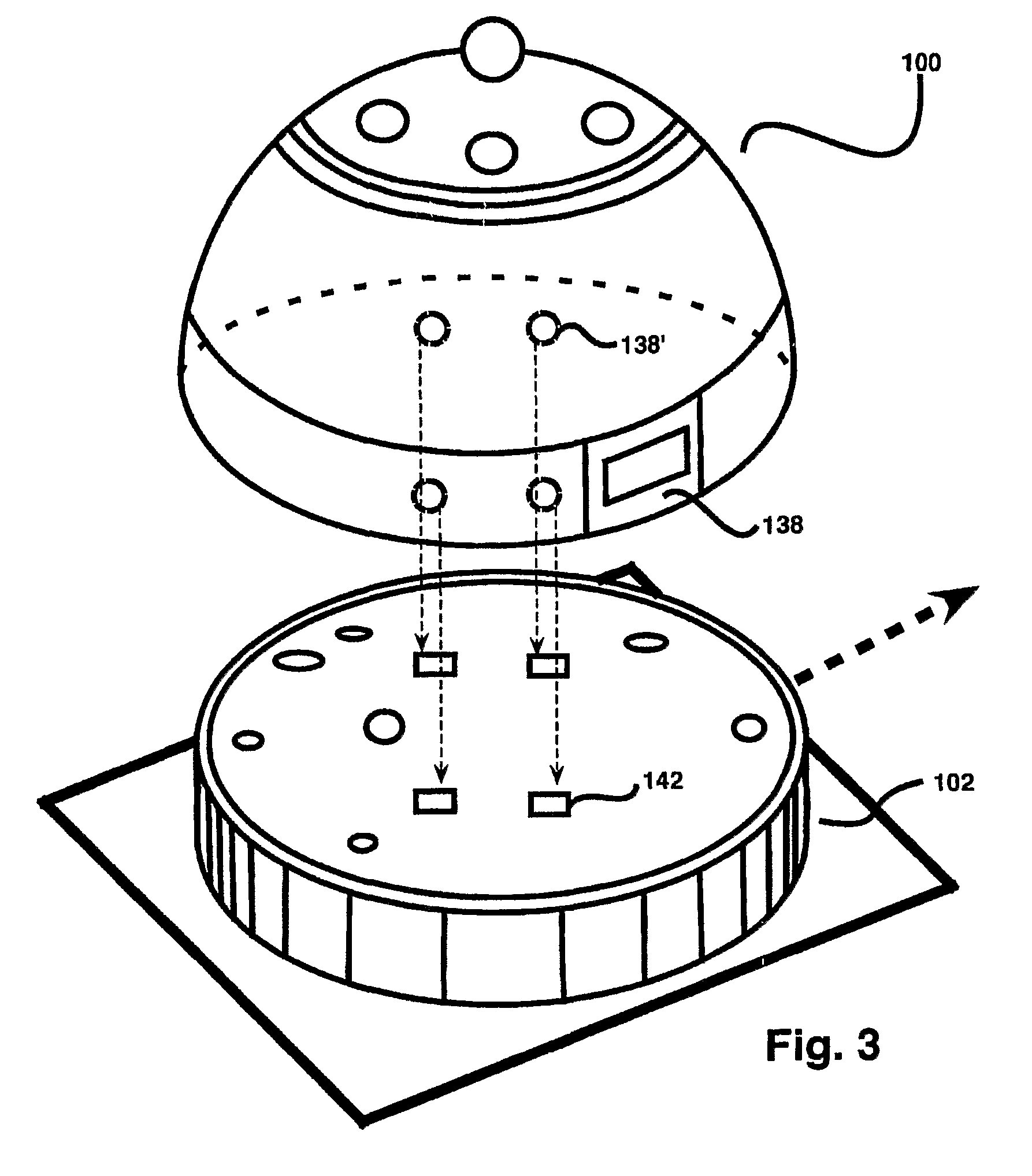
[0037]FIGS. 1 and 2 show a modified robotic floor cleaner, such as a modified FLOOR GENIE™, I-ROBOT® SCOOBA, or I-ROBOT® ROOMBA. The floor cleaner incorporates sterile disposable elements. FIG. 1 shows a Robotic Floor Cleaner with Cartridge 100 with cover 110 shown in a cutaway view to reveal its interior, and to show the placement of some of the major components. Reference numeral 122 is the chassis of the reusable portion of the Robotic Floor Cleaner with Cartridge 100. Portion 102 below is a disposable unit that is re-supplied in a sterile pack, with connections to reusable chassis portion 122. An optional bumper 118 may be provided around the Robotic Floor Cleaner with Cartridge 100. Disposable Portion 102 of the Robotic Floor Cleaner with Cartridge 100 has wet scrubbing brushes 120′ at the front and brushes 120 at the rear. These are connected to, and driven by, motor 141 within the non-disposable, reusable portion 122. Cleaning fluid in reservoir 126 is sprayed through nozzles...


PUM


Abstract

An automated (robotic) floor cleaner (100) is adapted to allow sterile cleaning of sensitive environments, such as hospital room. In particular, the floor-cleaner chassis (124) is redesigned to be mounted on a deck (102) containing cleaning devices that contact the floor. The cleaning devices mounted on the deck (102) include vacuum head (132), brushes (120), cleaning fluid sprays (128), and conceivably sanitizing devices such as UV germicidal light, are provided pre-sterilized. As such, the adapted floor-cleaner chassis (124) allows the deck (102) to be mounted to the bottom of the chassis (124), the floor-cleaner (100) is then used to clean a floor, after which, the deck (102) is removed from the chassis (124) and disposed. The robotic-floor cleaner (100) and sterilization system cleans floor between or even during cases. Further, the robotic floor cleaner (100) reduces the “turnover time” required between cases, as it operates simultaneously while the staff prepares the room for the next case.

Description

CROSS-REFERENCE TO RELATED APPLICATIONS[0001]This application is a national stage of application serial no. PCT / US06 / 28228, filed Jul. 20, 2006, which claims the benefit under 35 U.S.C. §119(e) of U.S. Provisional Application No. 60 / 701,106, filed Jul. 20, 2005, the contents of all of which are incorporated herein in their entireties by reference thereto.[0002]The following references are hereby explicitly incorporated by reference thereto:[0003]U.S. Pat. No. 6,605,156 B1[0004]U.S. Pat. No. 6,883,201[0005]Applications filed along with present application by current inventor on this date entitled:[0006]IN-CEILING FOCUS LOCATED SURGICAL LIGHTING[0007]HOSPITAL OPERATING ROOM RE-DESIGN[0008]AMBIENT LIGHTING IN HOSPITAL SURGICAL ENVIRONMENTS[0009]USE OF ULTRAVIOLET GERMICIDAL IRRADIATION IN HEALTH CARE ENVIRONMENTS[0010]IN-WALL WASTE RECEPTACLES FOR HOSPITAL AND LABORATORY ENVIRONMENTS[0011]MULTIFUNCTIONAL FLOOR PODS[0012]RE-DESIGN OF OPERATING ROOM TABLESBACKGROUND OF THE INVENTION[0013...

Claims


Application Information

Patent Timeline
Patent Type & Authority Patents(United States)
IPC IPC(8): A47L5/00A47L11/00G06F19/00
CPCA47L11/302A47L11/40A61B19/0287A61B19/0288B01L1/50B65F1/0093B65F1/06E04B5/48A47L2201/00A61B2019/0202A61B2019/025A61B2019/0267H01R13/005H01R27/02A61B2050/314A61B2050/005A61B50/13A61B50/36A61B50/362
Inventor MANGIARDI, JOHN R.
Owner OPTIMUS LICENSING AG
Why Eureka
Try Eureka