
Rotorcraft with opposing roll mast moments, and related methods

a technology of rotorcraft and roll mast, applied in the field of rotorcraft, can solve the problems of limited roll mast moment and more mechanical control authority, and achieve the effects of reducing the angle of attack and lift of the retreating blade, reducing the vibration level of the blade and the rotorcraft, and reducing the oscillatory load and rotorcraft vibration level of the blade and rotor

Active Publication Date: 2012-03-06
KAREM ABE
View PDF12 Cites 9 Cited by
  • Summary
  • Abstract
  • Description
  • Claims
  • Application Information

AI Technical Summary

Benefits of technology

"The patent describes a way to increase the lift of one blade and decrease the lift of another blade on a rotor, which reduces the load on the rotor and reduces vibration. This is achieved by applying a roll moment to the rotor and countering it with an equal and opposite roll moment on the other rotor. This results in a net reduction of cyclic applied to the rotor, potentially reducing the required control input. The method also reduces the stalled area of the blade, resulting in higher reliability and longer life for the rotor and lower crew fatigue. Overall, this method improves the performance and reliability of rotorcraft equipped with more than one lift producing rotor."

Problems solved by technology

The roll mast moment is limited by the mast moment capability of the particular rotor, and by the structural strength of the connecting devices between one rotor and another such as fixed and rotating masts, gearboxes, attachments and airframe.
The proposed scheme will also result in a net reduction of cyclic applied to the rotors, potentially resulting in more mechanical control authority.

Method used


Image

  • Rotorcraft with opposing roll mast moments, and related methods
  • Rotorcraft with opposing roll mast moments, and related methods
  • Rotorcraft with opposing roll mast moments, and related methods

Examples


Embodiment Construction

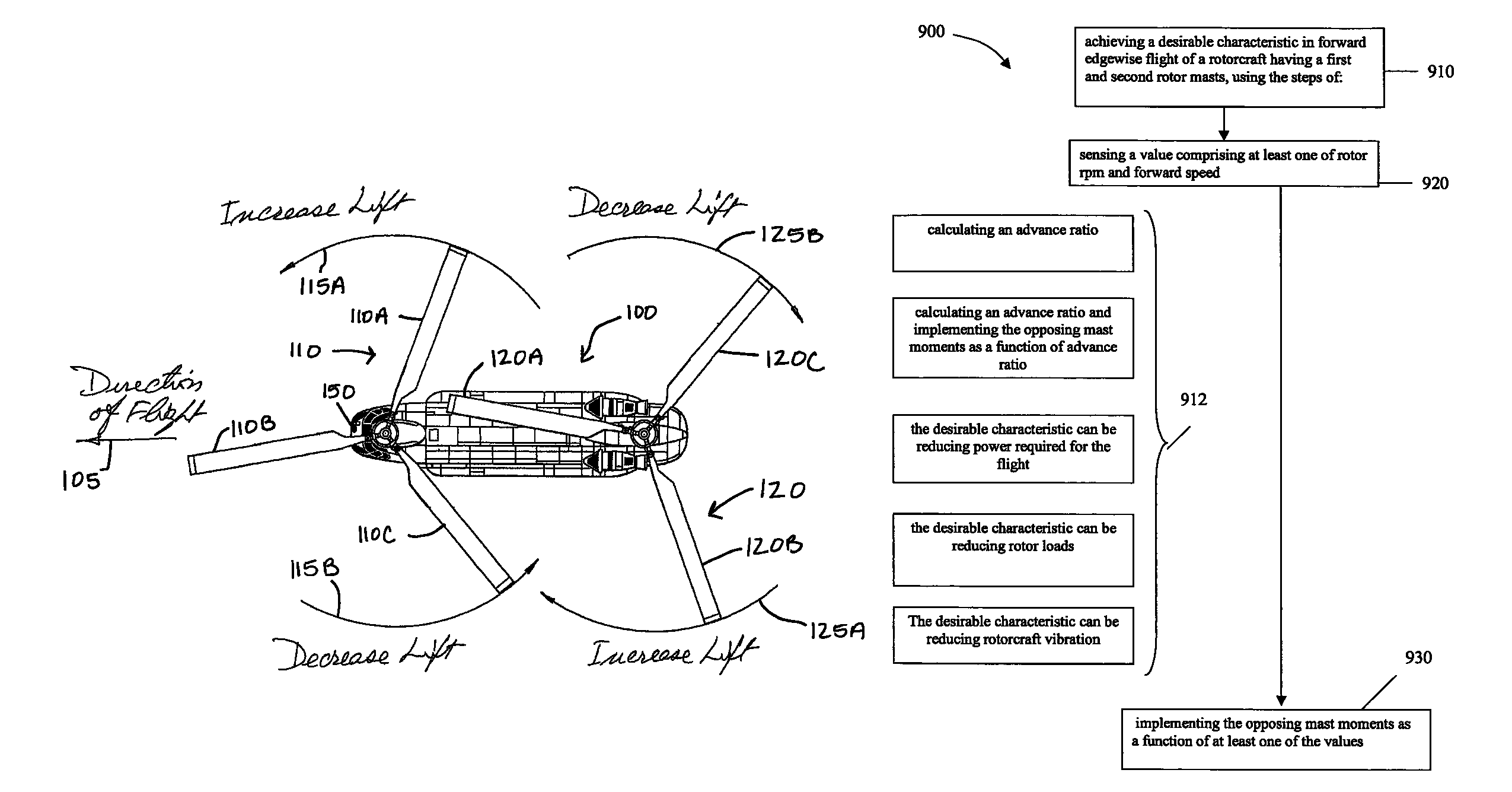
[0025]In FIG. 3, a twin tandem-rotor rotorcraft 100 is capable of moving in a forward direction of flight 105 using forward rotor 110 and aft rotor 120. Forward rotor 110 includes blades 110A, 110B, and 110C, and rotates in a counterclockwise direction. Aft rotor 120 includes blades 120A, 120B, and 120C, and rotates in a clockwise direction.

[0026]In a manner similar to that known for rotorcraft having rigid or semi-rigid co-axial rotors, a control mechanism 150 applies higher lift on the advancing blade of each rotor so that the mast moments on the two rotors substantially (i.e. except for the desired control rolling moment) cancel each other out. In this particular example, at the instant of the drawing, increased lift would be applied to blade 110A of rotor 110, and 120B of rotor 120. Of course, the situation changes as blades rotate to different positions, but in general it can be said that relatively increased lift is applied to blades of rotor 110 when positioned in the directi...


PUM


Abstract

In rotorcraft having rotors on multiple masts, a controller causes opposing roll mast moments to be applied to the different rotors. In preferred embodiments, the opposing roll moment is the result of increasing the lift on the advancing blade and reducing the lift on the retreating blade on the second rotor. This can be accomplished in any suitable manner, such as by applying differential cyclic roll control to the two rotors by tilting the two Swashplates of the two rotors or by using Individual Blade Control (IBC).

Description

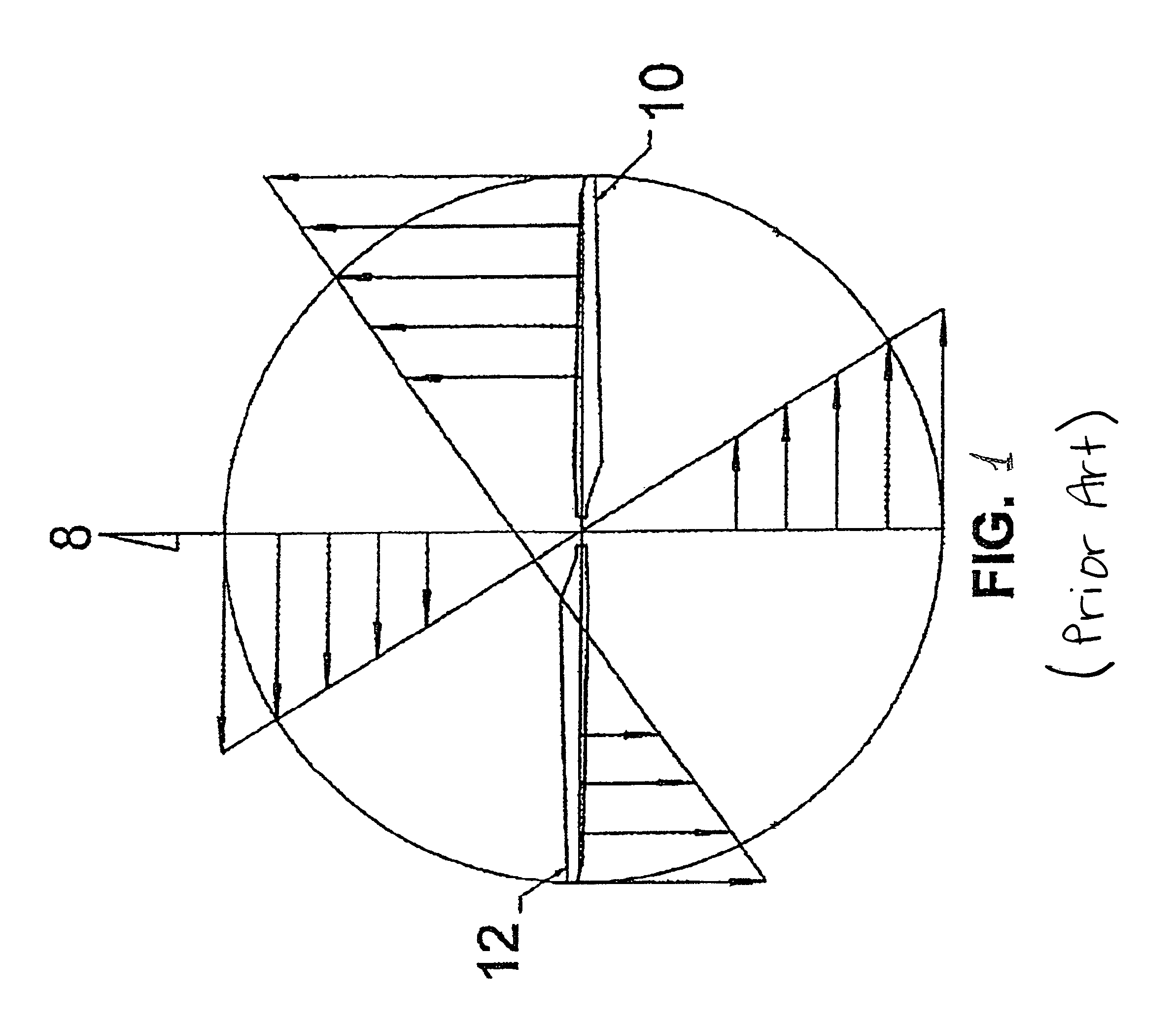
[0001]This application claims priority to U.S. Provisional Application Ser. No. 60 / 708,645 filed Aug. 15, 2005.FIELD OF THE INVENTION[0002]The field of the invention is rotorcraft having multiple rotors.BACKGROUND OF THE INVENTION[0003]In hover, each of the rotating blades of known rotorcraft rotors have the same airspeed, angle of attack and lift coefficient. Obviously, in forward flight, the blade rotating in the direction of the flight (advancing blade) will have its effective airspeed increased by the forward motion of the rotorcraft, i.e. effective velocity is equal to angular velocity plus vehicle velocity. Similarly, the blade rotating opposed to the direction of the flight (retreating blade) has its effective airspeed reduced by the vehicle velocity. (see FIG. 1).[0004]Rotors generally comprise aerodynamically shaped blades attached to a rotating mast at the center of rotation. In some rotors (teetering rotors) the blades are attached to hub which is free to teeter one blade...

Claims


Application Information

Patent Timeline
Patent Type & Authority Patents(United States)
IPC IPC(8): B64C13/18B64C27/08
CPCB64C27/08
Inventor KAREM, ABE
Owner KAREM ABE
Learn More