
Fluorine gas generator
a technology of fluorine gas and generator, which is applied in the direction of electrolytic organic production, manufacturing tools, instruments, etc., can solve the problems of difficult safe treatment of certain gases, short supply, and difficulty in storing certain amounts of gas, so as to simplify the piping between the electrolyzer and the water heating devi
- Summary
- Abstract
- Description
- Claims
- Application Information
AI Technical Summary
Benefits of technology
Problems solved by technology
Method used
Image

Examples
Embodiment Construction
[0029]In the following, a typical embodiment of the fluorine gas generator of the invention is described referring to the accompanying drawings.
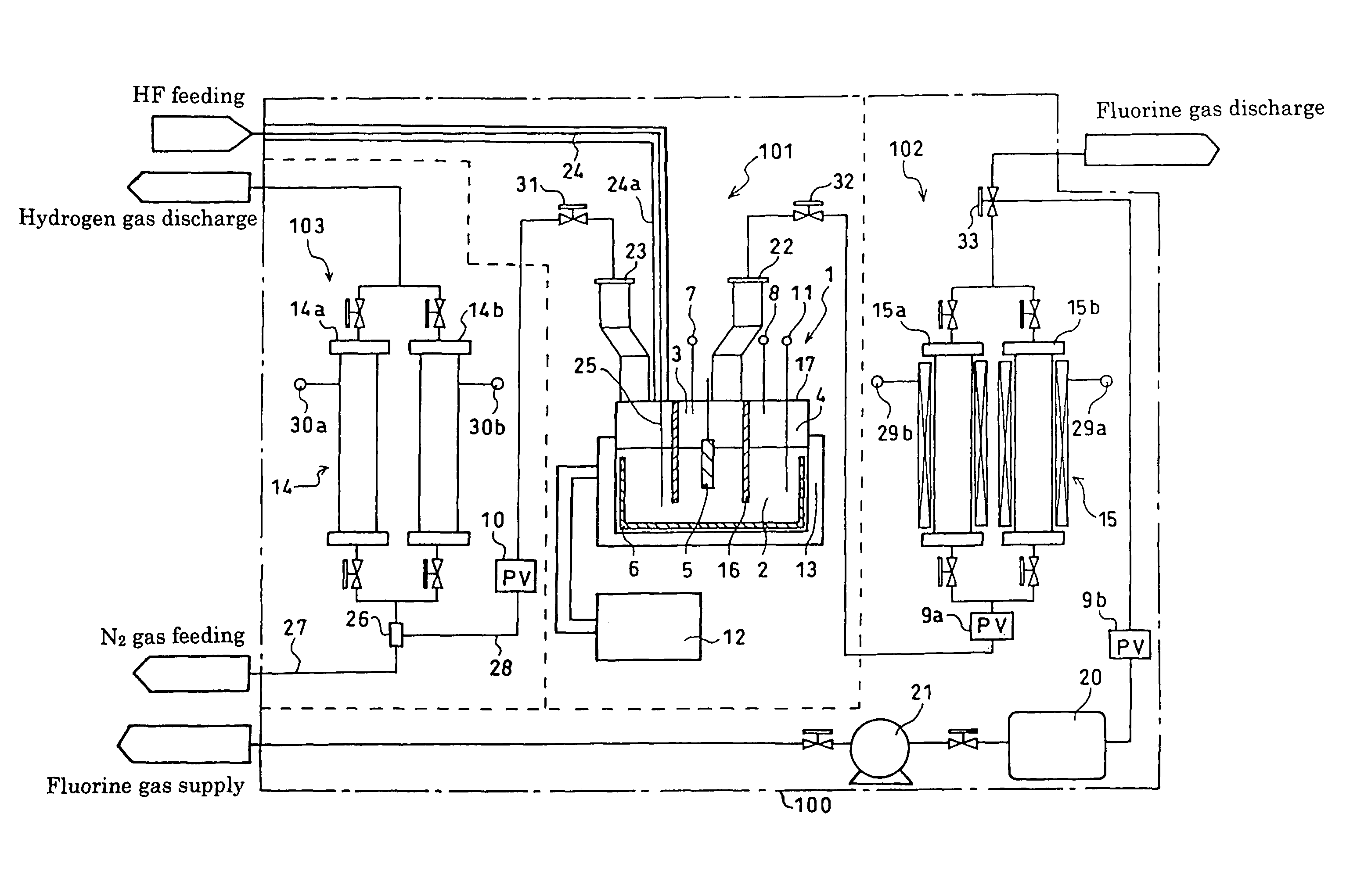
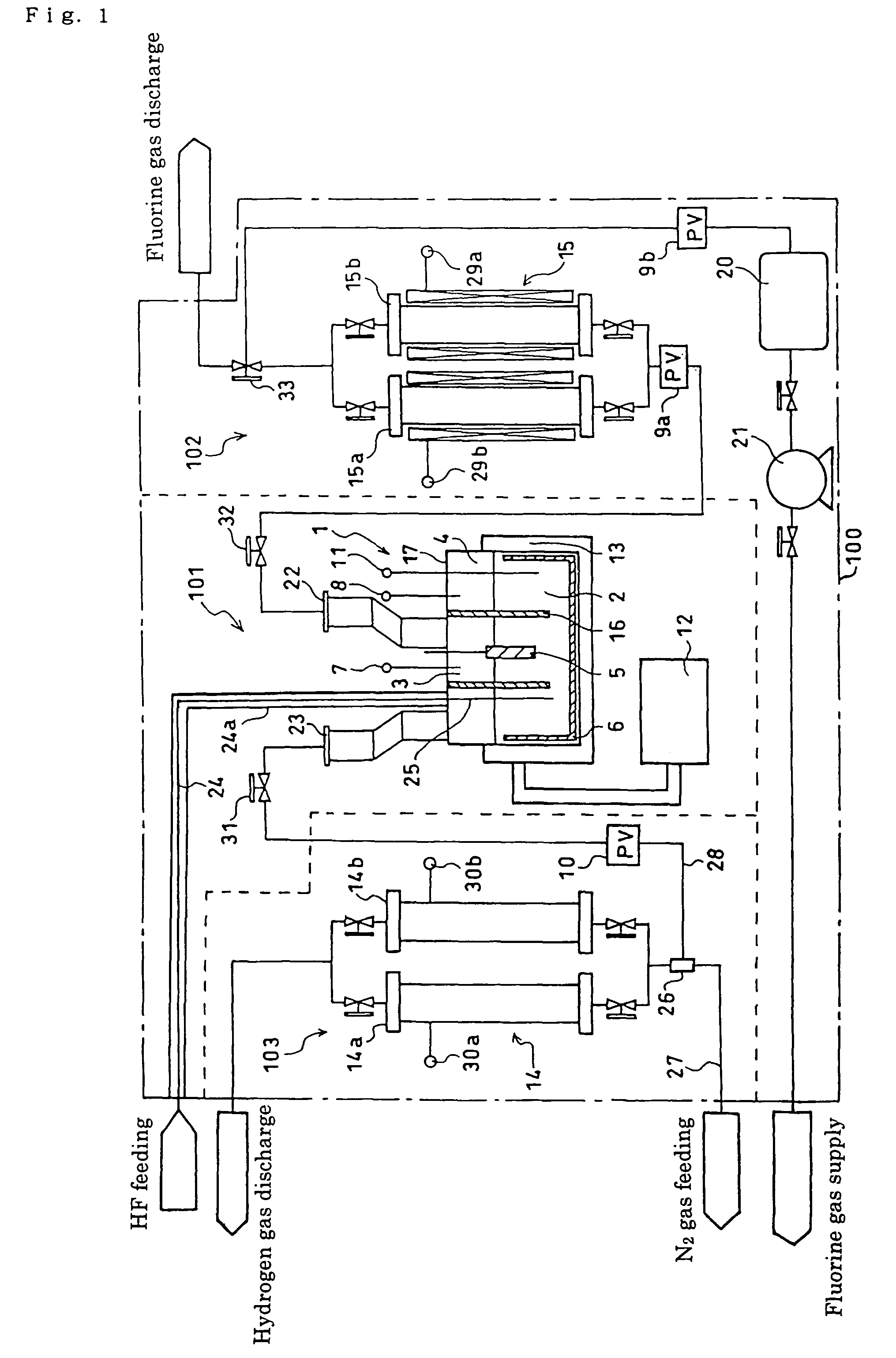
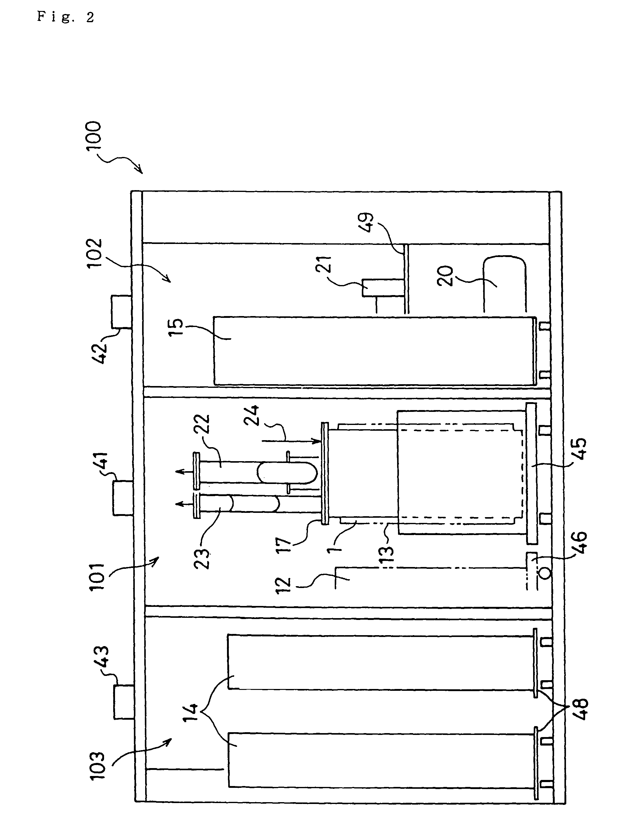
[0030]FIG. 1 is a schematic representation of the main parts of a fluorine gas generator according to the invention. In FIG. 1, the section 100 surrounded by a dot-and-dash line indicates a box-shaped body. As shown in FIG. 2 and FIG. 3, the box-shaped body 100 has an approximately rectangular shape. The inside of this box-shaped body 100 is divided into a first compartment 101, a second compartment 102, and a third compartment 103. This partitioning is realized by means of partition walls 105 and 106 extending from top to bottom. Due to the partitioning effect of these partition walls 105 and 106, the gases in different compartments cannot be mixed together. In FIG. 1, the portion 101 surrounded by a broken line indicates the first compartment, the portion 102 the second compartment, and the portion 103 the third compartment.
[0031]In the fi...
PUM
| Property | Measurement | Unit |
|---|---|---|
| suction | aaaaa | aaaaa |
| purity | aaaaa | aaaaa |
| pressure | aaaaa | aaaaa |
Abstract
Description
Claims
Application Information