
System for detecting proximity between a wind turbine blade and a tower wall

a technology for wind turbines and tower walls, applied in wind turbines, mechanical power/torque control, wind motors with parallel air flow, etc., can solve the problems of increasing the risk of turbine blades striking the tower, fatigue of turbine blades and other wind turbine components, and increasing the risk of turbine blades being struck by the tower

Active Publication Date: 2012-03-06
GE INFRASTRUCTURE TECH INT LLC
View PDF17 Cites 19 Cited by
  • Summary
  • Abstract
  • Description
  • Claims
  • Application Information

AI Technical Summary

Benefits of technology

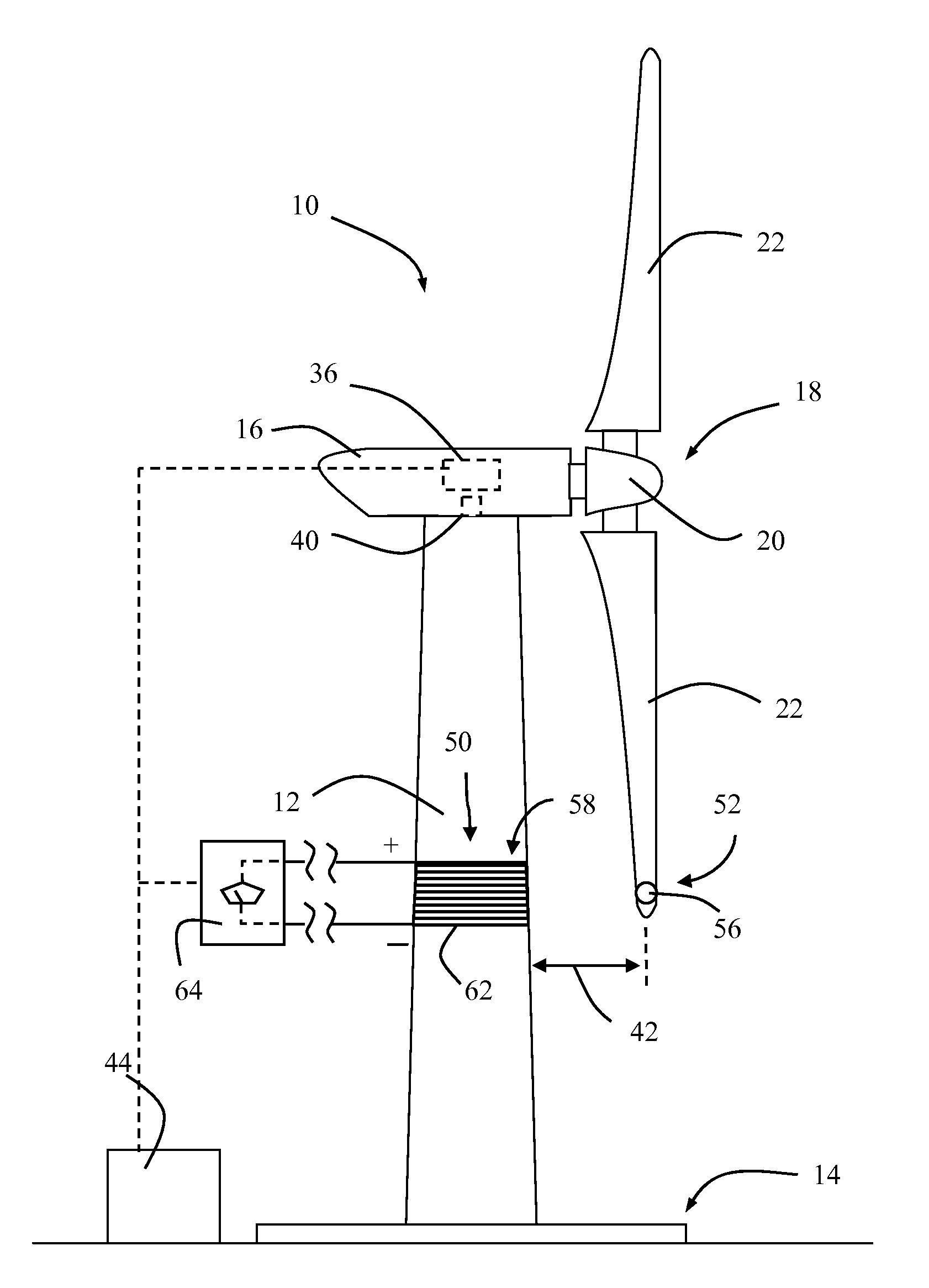
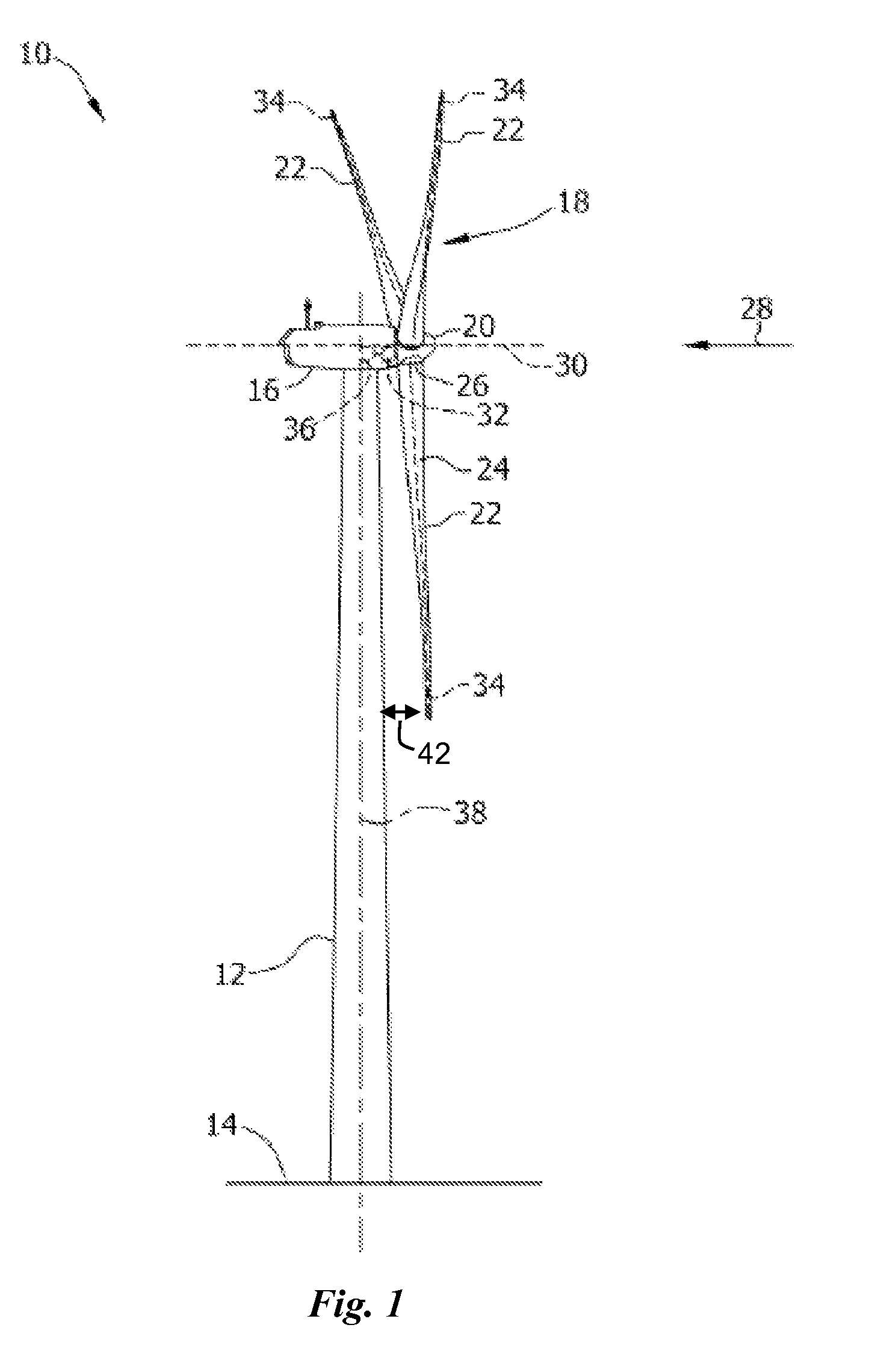
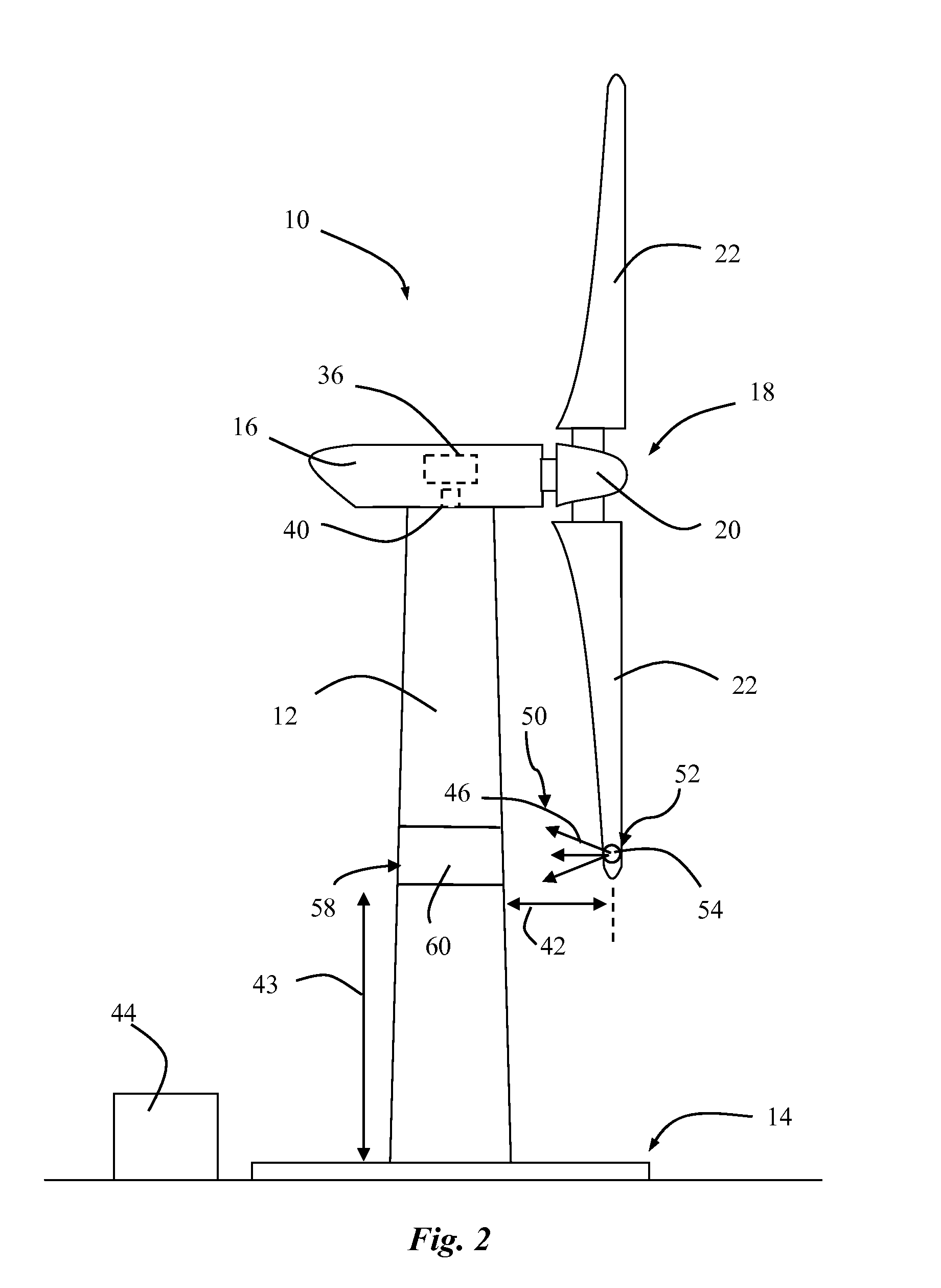
[0008]In one aspect, a unique sensor system is provided for monitoring deflection of turbine blades of any manner of wind turbine that includes at least one blade mounted to a rotor hub supported by a nacelle atop a tower. The system includes a first component configured on each of the turbine blades and a second component configured on the tower at a height so as to detect the presence of the first component as the blades rotate past the tower. The second component generates a corresponding parameter or value, such as a voltage or current, which indicates the distance between the blades and tower. The second component is disposed substantially completely around the circumference of the tower so as to detect the blades at any rotational position of the nacelle relative to the tower.

Problems solved by technology

Thus, longer turbine blades are subject to increased deflection forces, particularly when a wind turbine is operating in high wind speed conditions.
These increased deflection forces not only produce fatigue on the turbine blades and other wind turbine components, but may also increase the risk of the turbine blades striking the tower.
A tower strike can significantly damage a turbine blade and the tower and, in some instances, can even bring down the entire wind turbine.
The conventional sensors and associated systems are relatively complex and costly, and calibrating such sensors can be quite complex and time consuming.
Moreover, the sensors are generally limited to detecting the presence of the blade at a single circumferential location on the tower.
However, the nacelle can assume virtually any rotational position relative to the tower, which may result in the blades passing the tower on the opposite side of the sensor (i.e., receiver or transmitter component) mounted on the tower.

Method used


Image

  • System for detecting proximity between a wind turbine blade and a tower wall
  • System for detecting proximity between a wind turbine blade and a tower wall
  • System for detecting proximity between a wind turbine blade and a tower wall

Examples


Embodiment Construction

[0018]Reference now will be made in detail to embodiments of the present subject matter, one or more examples of which are illustrated in the drawings. Each example is provided by way of explanation, not limitation of the present subject matter. In fact, it will be apparent to those skilled in the art that various modifications and variations can be made in the present subject matter without departing from the scope or spirit of the present subject matter. For instance, features illustrated or described as part of one embodiment can be used with another embodiment to yield a still further embodiment. Thus, it is intended that the present subject matter covers such modifications and variations as come within the scope of the appended claims and their equivalents.

[0019]FIG. 1 illustrates a perspective view of a horizontal-axis wind turbine 10. However, it should be appreciated that the wind turbine 10 may be a vertical-axis wind turbine. The wind turbine 10 includes a tower 12 that ex...


PUM


Abstract

A sensor system monitors deflection of turbine blades of a wind turbine. The system includes a first component configured on the turbine blades. A second component is configured on the tower at a height so as to detect the presence of the first component as the blades rotate past the tower. The second component generates a corresponding measurable parameter or value that is indicative of distance between the blades and tower. The second component is disposed substantially completely around the circumference of the tower so as to detect the first components at any rotational position of the turbine nacelle relative to the tower.

Description

FIELD OF THE INVENTION[0001]The present subject matter relates generally to wind turbines, and more particularly to a system for detecting the proximity of the turbine blades relative to the in order to prevent a tower strike.BACKGROUND OF THE INVENTION[0002]Wind power is considered one of the cleanest, most environmentally friendly energy sources presently available, and wind turbines have gained increased attention in this regard. A modern wind turbine typically includes a tower, generator, gearbox, nacelle, and one or more turbine blades. The turbine blades capture kinetic energy from wind using known foil principles and transmit the kinetic energy through rotational energy to turn a shaft coupling the rotor blades to a gearbox, or if a gearbox is not used, directly to the generator. The generator then converts the mechanical energy to electrical energy that may be deployed to a utility grid.[0003]To ensure that wind power remains a viable energy source, efforts have been made to...

Claims


Application Information

Patent Timeline
Patent Type & Authority Patents(United States)
IPC IPC(8): G05D3/12B64C11/00B63H1/00B63H3/00F01D25/00F01D5/00F01D5/18B64C27/00H02P9/04F03D9/00G05D5/00
CPCF03D7/0288F03D11/0091G01B7/14F03D11/04F03D1/0675F05B2270/33Y02E10/723Y02E10/726Y02E10/728F05B2240/912Y02E10/721F05B2270/17F03D17/00F03D13/20F03D9/25Y02E10/72
Inventor NEUMANN, ULRICH
Owner GE INFRASTRUCTURE TECH INT LLC
Learn More