Method for recovering valuable drilling mud materials using a binary fluid

a technology of binder fluid and drilling mud, which is applied in the direction of filtration separation, separation process, borehole/well accessories, etc., can solve the problems of inability to fully utilize the remedies of lcm/lpm, inability to recover and recycle, and inability to fully utilize the strengthening and circulation of the wellbor

Active Publication Date: 2012-03-13
CONOCOPHILLIPS CO
View PDF17 Cites 9 Cited by
  • Summary
  • Abstract
  • Description
  • Claims
  • Application Information

AI Technical Summary

Problems solved by technology

Wellbore strengthening and lost circulation remedies using LCM / LPM may not be fully utilized because it is impractical to recover and recycle the materials used to in these operations and also to process the drilling fluid to remove the drill cuttings and undesirable drill solids.
Blow outs and kicks are very dangerous and destructive.
Weighting agents are finely ground materials which make the removal of fine drill solids by processing equipment such as hydrocyclones and rotating centrifuges considerably less efficient.
As the LCM / LPM materials and weighting agents are solids, they interfere with the efficient removal of drill cuttings and other undesirable solids because the particles have similar size or mass.
Since such materials have not been very expensive, there has been little incentive to consider ways to recover or recycle these materials.
However, advances in wellbore strengthening technology, improved LPM materials and an increasingly limited supply of quality weighting materials has created the need for improved methods for the recovery and recycling for drilling fluids materials.
At the same time, petroleum drilling operations in remote areas makes disposable materials more expensive when one considers the logistical costs of shipping such materials and maintaining large inventories of the same, particular in offshore or small worksite locations.

Method used


Image

  • Method for recovering valuable drilling mud materials using a binary fluid
  • Method for recovering valuable drilling mud materials using a binary fluid
  • Method for recovering valuable drilling mud materials using a binary fluid

Examples


Embodiment Construction

[0018]Turning now to the preferred arrangement for the present invention, reference is made to the drawings to enable a more clear understanding of the invention. However, it is to be understood that the inventive features and concept may be manifested in other arrangements and that the scope of the invention is not limited to the embodiments described or illustrated. The scope of the invention is intended only to be limited by the scope of the claims that follow.

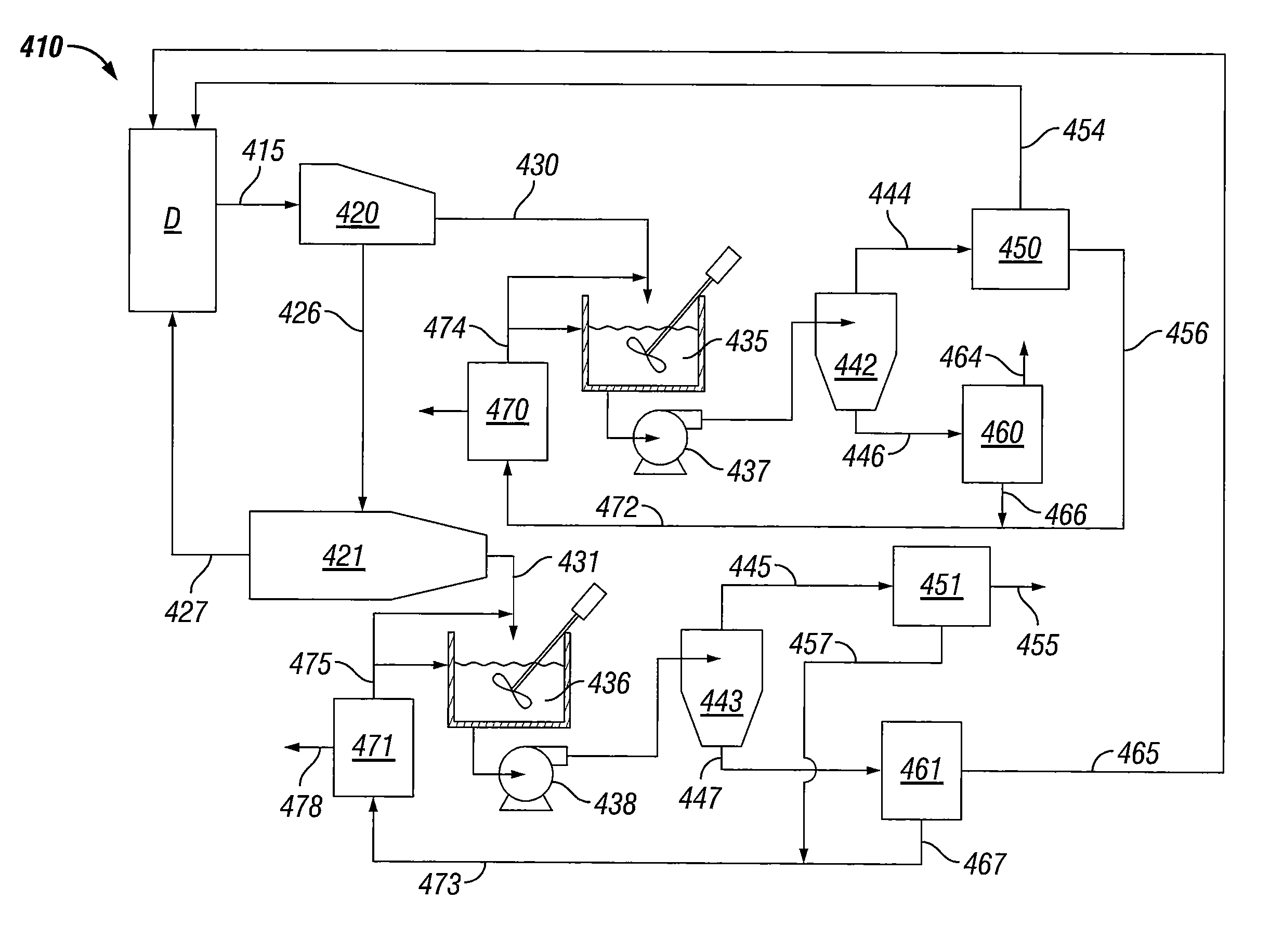
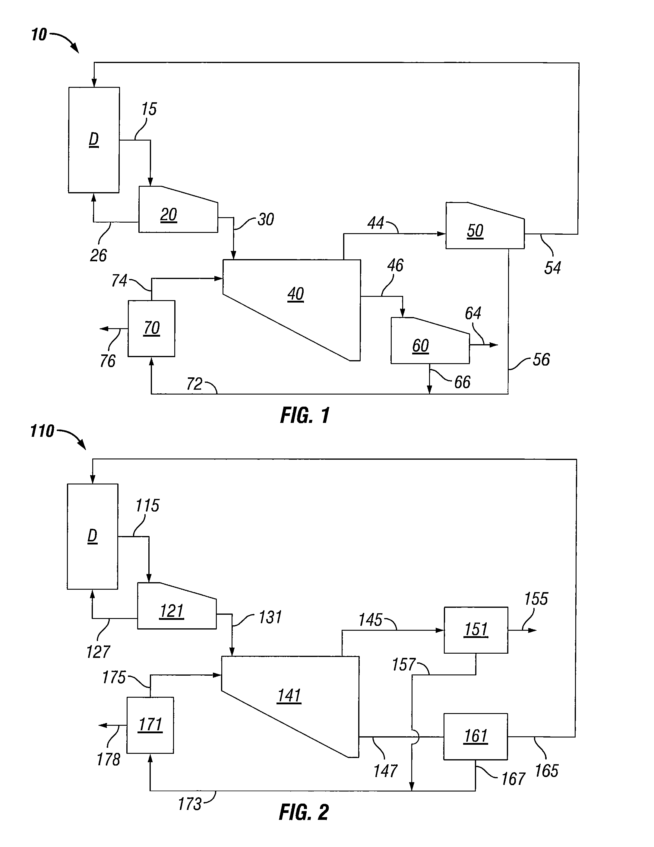
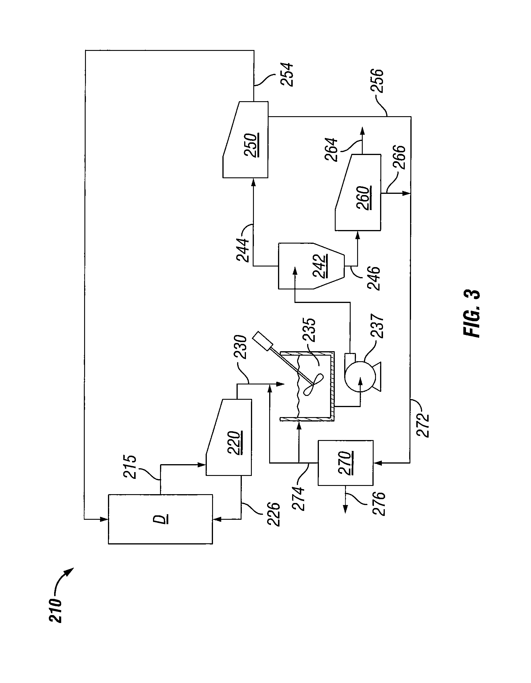
[0019]Referring initially to FIG. 1 which is a process flow diagram illustrating a first embodiment of a separation and recovery process generally indicated by the arrow 10 for removing solids from drilling fluid that has emerged from a wellbore with drill cuttings and similar materials derived from the hydrocarbon well drilling process. Once the solids are removed from the drilling fluid, the drilling fluid is directed to the drilling operation where it may be prepared for re-use. In the separation process 10, a drilling o...


PUM

PropertyMeasurementUnit
specific gravityaaaaaaaaaa
sizeaaaaaaaaaa
volumeaaaaaaaaaa

Abstract

This invention relates to a system and process for recovering and recycling valuable target recycle materials such lost circulation material and weighting agents from drilling fluid used in hydrocarbon drilling operations. The system and process includes use of a binary fluid that is separate from the drilling fluid and has a designed density that allows separation of the valuable target recycle materials from drill cuttings. The solids are separated from the drilling fluid in a primary separation step and then mixed with the binary fluid in a density separation or enhanced mass separation device. The binary fluid density allows the separation device to distinguish the target recycle material from drilling solids and recycles the target material to the drilling operations for re-use in drilling fluid. The binary fluid is recovered and refreshed to maintain a generally continuous process of targeted recycling.

Description

CROSS-REFERENCE TO RELATED APPLICATIONS[0001]The present application claims priority to U.S. Provisional Application No. 61 / 046,092, filed Apr. 18, 2008.STATEMENT REGARDING FEDERALLY SPONSORED RESEARCH OR DEVELOPMENT[0002]None.FIELD OF THE INVENTION[0003]The disclosure relates generally to systems and methods for recovery and recycling of solids from drilling muds for use in drilling operations.BACKGROUND OF THE INVENTION[0004]Drilling fluids, also commonly referred to as drilling mud or drilling muds, have been used for many years and provide a number of benefits for drilling. Drilling fluids are directed through the hollow axis of the drillstring to lubricate and cool the drill bit at the bottom of the well. The drilling fluids return to the surface in the annulus between the drillstring and the interior wall of the drillstring carrying drill cuttings (rocks, sand, shale, grit and other debris) back to the surface. At the surface, drilling fluids are processed to remove drill cutt...

Claims


Application Information

Patent Timeline
Patent Type & Authority Patents(United States)
IPC IPC(8): E21B21/01E21B21/06
CPCE21B21/066
Inventor SCOTT, PAUL D.
Owner CONOCOPHILLIPS CO
Why Eureka
Try Eureka