Eureka AIR delivers breakthrough ideas for toughest innovation challenges, trusted by R&D personnel around the world.

Speaker system

a technology of speaker system and speaker body, which is applied in the direction of cabinet, cabinet, cabinet/cabinet/drawer of electric apparatus, etc., to achieve the effect of reducing the degree of freedom of downsizing, improving the design of the device, and suitable results

Inactive Publication Date: 2012-03-13
SNEXT
View PDF44 Cites 1 Cited by
  • Summary
  • Abstract
  • Description
  • Claims
  • Application Information

AI Technical Summary

Benefits of technology

[0010]A speaker system according to the present invention does not need depth, and also in the case of fixed to a device emitting sounds forward, it can avoid having limitation in the attaching position and the attaching area of a speaker in designing. Further, it becomes unnecessary to provide the opening of a speaker on the front surface of a device. Therefore, the degree of freedom in downsizing and a design of the device is remarkably improved. More particularly, by practically using to a thin-type device, suitable results can be obtained.

Problems solved by technology

Moreover, in a device in that the area to attach a speaker cannot be sufficiently secured as a front panel of a television receiving set, a sealed or a semi-sealed space is secured by placing the main body of a speaker in the back space of a cabinet of a television receiving set.

Method used


Image

  • Speaker system
  • Speaker system
  • Speaker system

Examples


embodiment 1

[0052]Hereinafter, embodiments of the present invention will be described with reference to drawings. Note that, in the embodiments 1 to 3, the aforementioned air flow resistance element 63 existing at the opening end of the waveguide is omitted to be shown in the drawings to simplify.

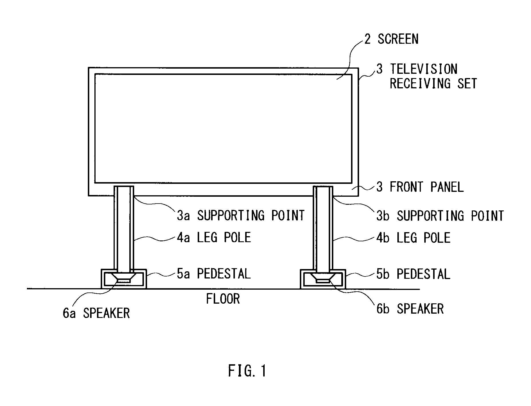
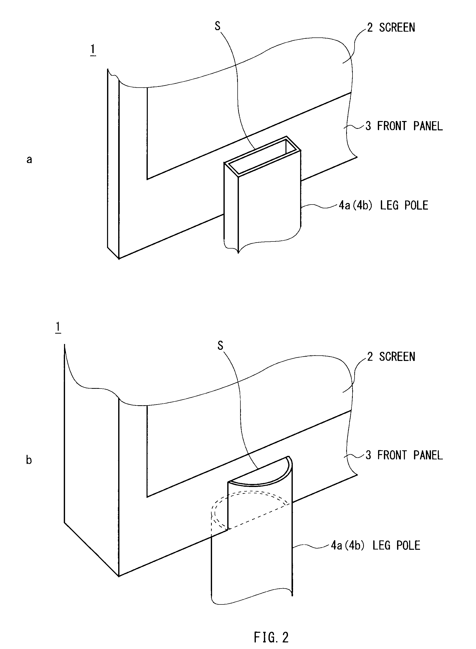
[0053]FIG. 1 is an example of the case where the present invention is practiced to a thin-type television receiving set. It is a view of the television receiving set from the front. Specially, the part of the leg poles 4a and 4b and the pedestals 5a and 5b that will be described later are represented by sections so as to know the structure. Referring to FIG. 1, a reference numeral 1 designates a main body of a television receiving set, and a reference numeral 2 designates the screen. The main body of the television receiving set 1 is supported by two leg poles 4a and 4b attached to supporting points 3a and 3b on the lower frame of a front panel 3. The leg poles 4a and 4b are formed to be hollow, and al...

embodiment 2

[0060]FIG. 3 is an embodiment when a speaker system according to the present invention is applied to an audio system for automobile. FIG. 3 is a side view when the driver's seat is looked from the passenger's side. A reference numeral 31 designates the driver's seat, a reference numeral 32 designates a steering eel, a reference numeral 33 designates a door, and a reference numeral 34 designates a door glass. A reference numeral 35 designates a speaker. However, usually it is built into the interior space of the door or into a wall near foot, and only a speaker grill is exposed on the surface. Therefore, a sound emitted from the speaker 35 is usually emitted near the driver's foot, in addition, toward horizontal directions.

[0061]In the embodiment 2 shown in FIG. 3, a speaker cabinet (not shown) is built into the lower space of the door 33, and a waveguide 36 is attached so as to cover the front of the diaphragm of the speaker 35. And the waveguide 36 is passed so as to pass through t...

embodiment 3

[0062]FIG. 4 represents a third embodiment when the present invention is practically used in a game device. Referring to FIG. 4, a reference numeral 40 designates a Japanese pinball machine. This type of device will be installed in a height as that player's face comes to just the center of the face of the board, and normally it has a speaker individually to play a sound as uplifting the player's mental state. However, speakers 42 cannot be installed in the height of a player's face (ears) in relation to attached space, and are attached to empty spaces such as the corners of the left, right, top and bottom. The face of the board is covered with a clear glass (not shown) put in a frame 41.

[0063]In this embodiment, a waveguide 43 is attached to a proper place such as the interior, front, back of the frame 41 of the Japanese pinball machine 40, and sound is led from the speakers 42 attached to the upper left and right corners of the Japanese pinball machine to the height of the player's...


PUM


Abstract

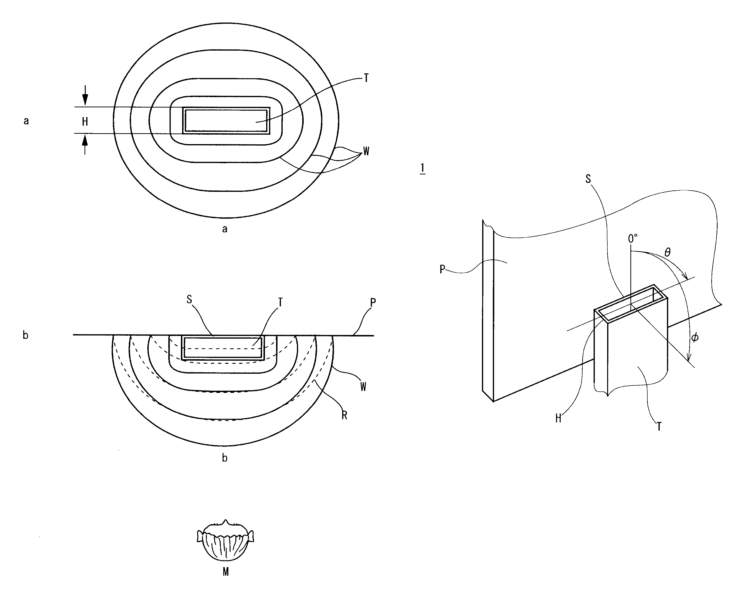
Normally a speaker is used by attaching to a sealed or semi-sealed cabinet so that vibration generated at the front and the back of a diaphragm does not mutually interfere. Therefore, a certain depth and a volume are necessary, and in a limited location such as a front panel of a device, there is a case that it cannot be attached to the most suitable position for a listener. As a means to solve that, a method that a speaker sound at a distant position is led to a front panel by a waveguide is practically used. However, still it has limitations in depth and attaching position, and good results cannot be obtained also in efficiency.A speaker is attached so that a sound generated at the front of the speaker attached to a cabinet is led to a plane such as a front panel of a device by a waveguide, and the opening surface of the waveguide is almost perpendicular to the plane. Since a good sound field is generated on the opposite side to the plane, on a horizontal surface to the opening surface of the waveguide, a high efficiency speaker system having no limitation in the attaching position of a speaker can be obtained.

Description

TECHNICAL FIELD[0001]The present invention relates to a speaker system or a device having a speaker system. Further, more particularly, the present invention relates to a speaker system in that a waveguide is attached to a speaker, and the opening surface of the waveguide is attached to a plane so as to be almost perpendicular to the plane, and a device having that.BACKGROUND ART[0002]Since a speaker generates sound waves by the vibration of diaphragm, the phases are shifted 180 degree between a vibration generated in front of the diaphragm and a vibration generated at the back. Therefore, in order to obtain good frequency characteristics and efficiency, it is necessary to avoid that the vibration generated at the back does not interfere with the vibration generated in front. As a fundamental structure, a sealed space or an almost sealed space is needed at the back.[0003]Moreover, in a device in that the area to attach a speaker cannot be sufficiently secured as a front panel of a t...

Claims


Application Information

Patent Timeline
Patent Type & Authority Patents(United States)
IPC IPC(8): A47B81/06G10K11/22H04R5/02G10K11/00G10K11/18H04R1/02
CPCH04R1/2857H04R2499/13
Inventor TAKASHIMA, MITSURU
Owner SNEXT
Why Eureka
Eureka Blog
Learn More