
Trailer ramp system

a trailer and ramp technology, applied in the field of trailer ramps, can solve the problems of undesirable separation of sections of ramps, considerable weight to be manually lifted, and heavy frame weight of ramps, and achieve the effects of convenient handling, sufficient biasing force, and great biasing assis

Active Publication Date: 2012-03-13
PAPROSKI VERN
View PDF4 Cites 4 Cited by
  • Summary
  • Abstract
  • Description
  • Claims
  • Application Information

AI Technical Summary

Benefits of technology

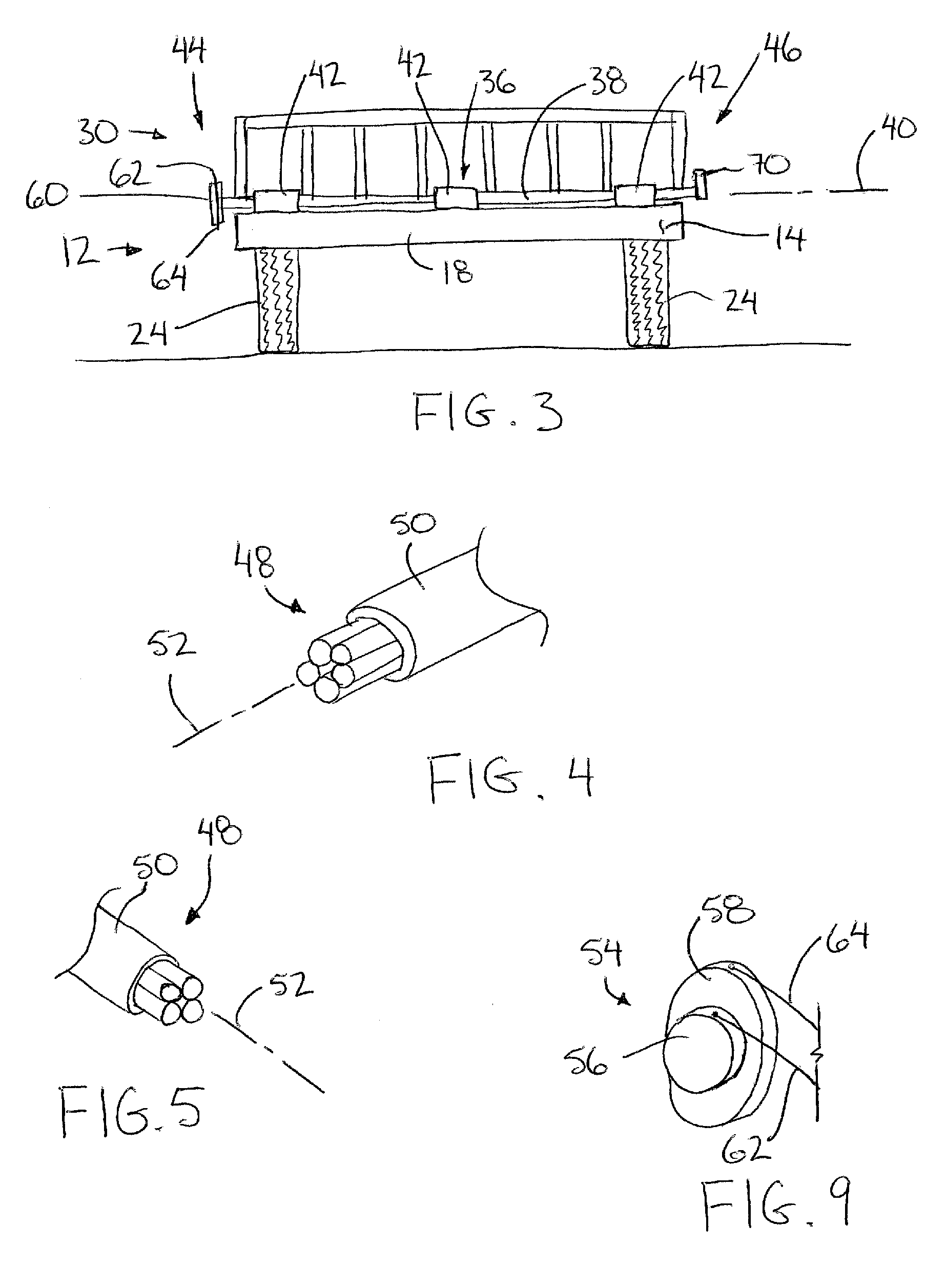
"The invention is a ramp system for a flat bed trailer that can be easily raised and lowered using a hinge pivot. The ramp is supported by a torsion member that is coupled to the deck frame and the ramp member. The torsion member is designed to bias the ramp member towards the intermediate position between the loading and storage positions. The use of a torsion member allows for a single operator to easily handle the entire ramp, making it safer and easier to operate. The ramp can be raised and lowered without adjusting the width between ramp sections, which is common with other designs. The torsion member can be coupled to the deck frame and the ramp member in a way that allows for a full width ramp surface in the loading position. The use of multiple torsion rods in each torsion member increases the torsional range of motion and minimizes wind drag. The torsion member can be coupled to the deck frame and the ramp member in a way that allows for a full width extension of the horizontal deck surface in the loading position. The use of torsion members also allows for an open frame design for the ramps, which reduces wind drag during transport."

Problems solved by technology

Both the frame of the trailer and of the ramps must be designed to carry a substantial amount of weight during loading and unloading operations and for carrying various objects and vehicles on the trailer, so that the resulting frames of the ramps may be quite heavy, for example being between 100 and 150 pounds for each section of the ramp.
Various prior art designs incorporate springs at the hinge coupling the ramps to the deck frame however the biasing provided by conventional spring designs typically limit the amount of weight to be carried so that even when forming the ramps in individual sections to reduce the weight thereof, a considerable weight remains to be manually lifted.
Furthermore forming the ramps as separate spaced apart sections is somewhat undesirable as there is a danger of a vehicle slipping off the sides of the narrow individual ramp sections during a loading or unloading operation.

Method used


Image

  • Trailer ramp system
  • Trailer ramp system
  • Trailer ramp system

Examples


Embodiment Construction

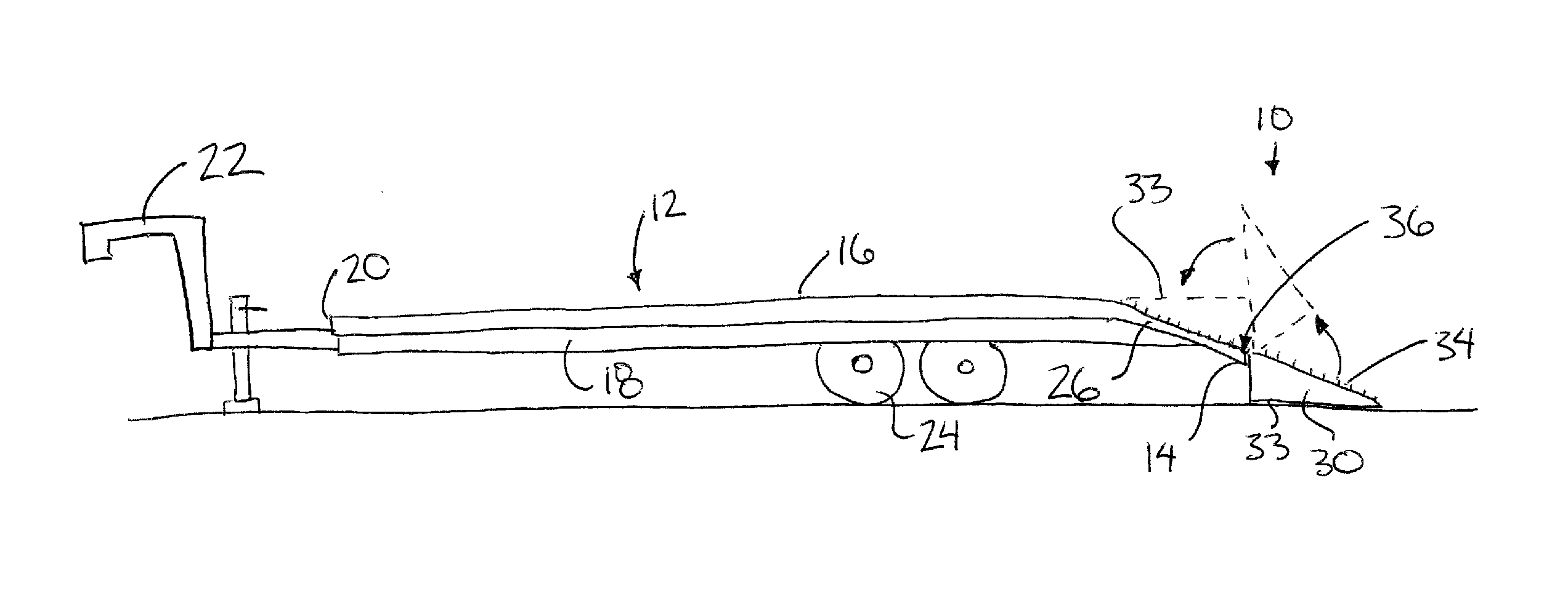
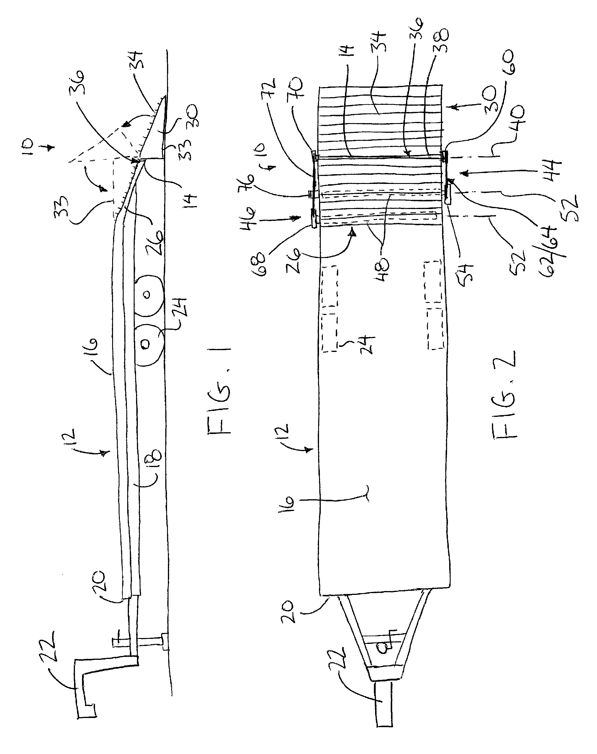
[0047]Referring to the accompanying figures there is illustrated a ramp system generally indicated by reference numeral 10. The ramp system 10 is particularly suited for use with a flat bed trailer 12 in which the ramp system 10 is supported at a rear end 14 of the trailer for loading objects and vehicles onto a flat upper deck surface 16 of the trailer.

[0048]The trailer includes a deck frame 18 supporting the deck surface 16 thereon to extend in a longitudinal direction from a front end 20, locating a hitch connector 22 of the trailer, to the rear end 14. The deck frame 18 is supported on wheels 24 for forward rolling movement in the longitudinal direction when towed by a towing vehicle coupled to the trailer by the hitch connector 22. The deck surface 16 includes a ramp portion 26 adjacent the rear end of the trailer in which the flat horizontal deck surface is inclined downwardly and rearwardly to the rear end 14 of the trailer in fixed orientation relative to the deck frame 18.

[...


PUM


Abstract

A ramp member is pivotally supported at the rear of a flat bed trailer for pivotal movement between a loading position extending from the flat bed to the ground and a storage position supported on the trailer bed, through an intermediate position between the loading position and the storage position. First and second torsion members are arranged such that at least one of the torsion members biases the ramp member from each of the loading and storage positions towards the intermediate position. The torsion members permit substantially a full weight of the ramp member to be counter-balanced through its full range of motion so that a single ramp member spanning a full width of a rear end of the trailer in the lateral direction can be manually displaced by a single operator.

Description

FIELD OF THE INVENTION[0001]The present invention relates to a ramp system for being pivotally mounted on a flat bed trailer in which a ramp includes a lift assist for assisting in lifting the ramp from a loading position relative to the trailer, and more particularly the present invention relates to a lift assist for a trailer ramp comprising a torsion member.BACKGROUND[0002]A common construction of heavy duty trailers involves an elongate flat bed deck supported on wheels in a suitable manner for rolling movement in a forward direction of a towing vehicle. A hitch connector at a forward end of the trailer secures the trailer to the towing vehicle. Ramps are typically pivotally coupled at a rear end of the trailer for loading objects onto the trailer deck surface. Typically there are two ramps spaced apart at an adjustable lateral spacing for accommodating the various wheel spacings of vehicles to be loaded onto the trailer deck surface. The ramps are typically hinged and rotate be...

Claims


Application Information

Patent Timeline
Patent Type & Authority Patents(United States)
IPC IPC(8): B60P1/04
CPCB60P1/438
Inventor PAPROSKI, VERN
Owner PAPROSKI VERN
Learn More