Method of auto calibrating a magnetic field sensor for drift and structure therefor

a magnetic field sensor and auto-calibration technology, applied in the direction of magnetic measurement, magnetic offset compensation, instruments, etc., can solve the problems of temperature variation, compensation circuits cannot compensate adequately for temperature variation, and the problem of not solving the problem of sensitivity variation

Active Publication Date: 2012-03-13
AMI SEMICON BELGIUM
View PDF6 Cites 72 Cited by
  • Summary
  • Abstract
  • Description
  • Claims
  • Application Information

AI Technical Summary

Benefits of technology

[0010]It is an object of embodiments of the present invention to provide good magnetic sensor devices or good methods for providing magnetic sensing.
[0012]In an aspect, the present invention proposes to isolate the contribution of a reference magnetic field BCal to the output signal of a magnetic sensor from the contribution of an external magnetic field BExt to the same output signal without having to use several sensors and / or specific filters as in the prior art. Having isolated the contribution from the reference magnetic field, it is easy to evaluate the sensitivity drift of the magnetic sensor generating the output signal and to compensate for said sensitivity drift.

Problems solved by technology

While the dynamic offset cancellation technique explained here above solves the problem of the offset, it does not solve the problem of variations of sensitivity.
If the temperature dependency of the sensitivity varies for one reason or another, those compensation circuits will not be able to compensate adequately for the temperature variations.
This is not always desired if the power available for operation of the sensor is limited and / or if the area of semiconductor substrate available to integrate the Hall sensors is limited.
Such a filter is not always easy to realize and furthermore consumes additional power and silicon area.

Method used


Image

  • Method of auto calibrating a magnetic field sensor for drift and structure therefor
  • Method of auto calibrating a magnetic field sensor for drift and structure therefor
  • Method of auto calibrating a magnetic field sensor for drift and structure therefor

Examples


first embodiment

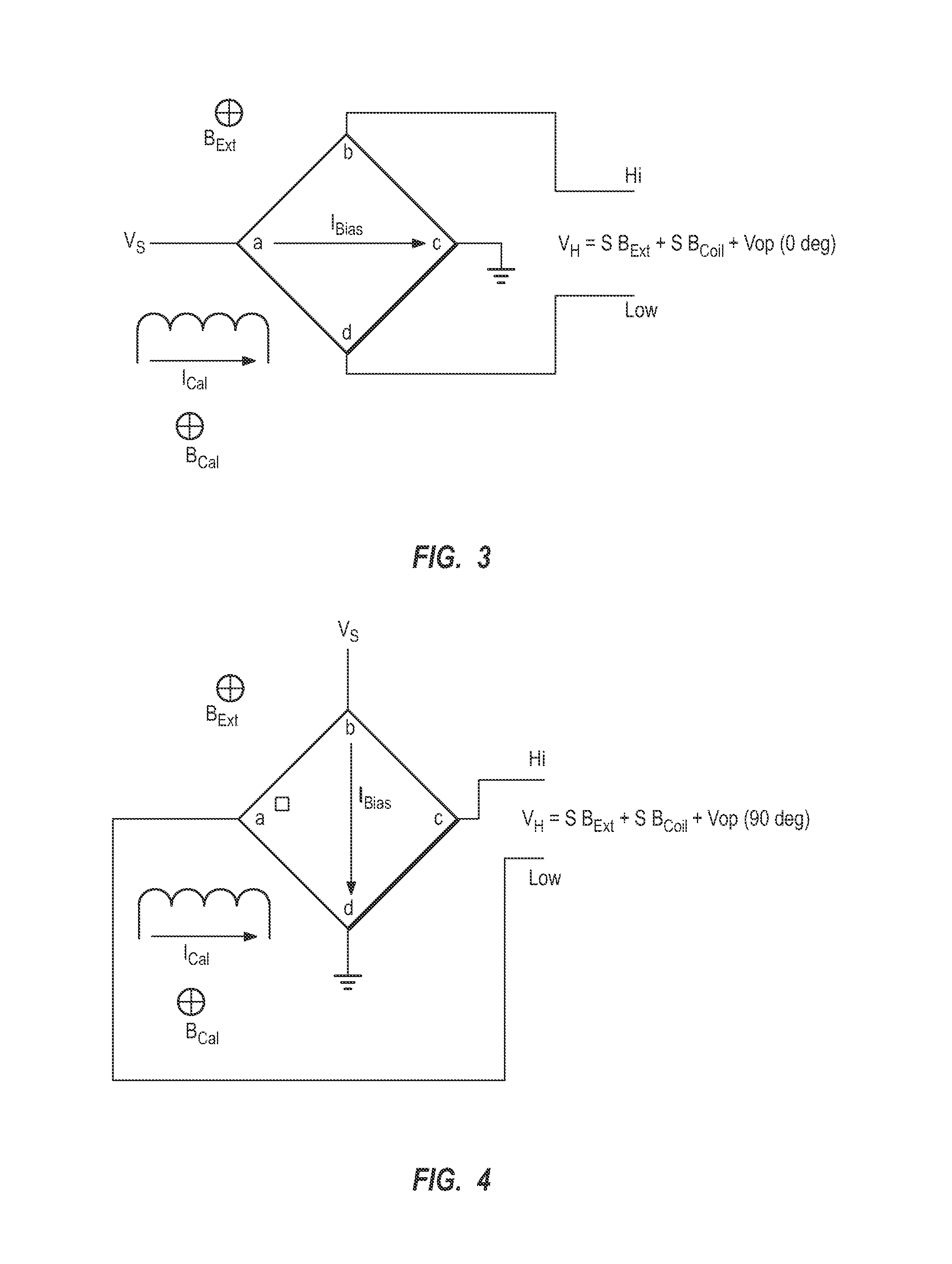
[0066]In a first embodiment, the present invention builds on the dynamic offset compensation method of the prior art described here above to separate the contribution of the offset, the external magnetic field BExt and the reference magnetic field BCal to the output signal of a Hall sensor.

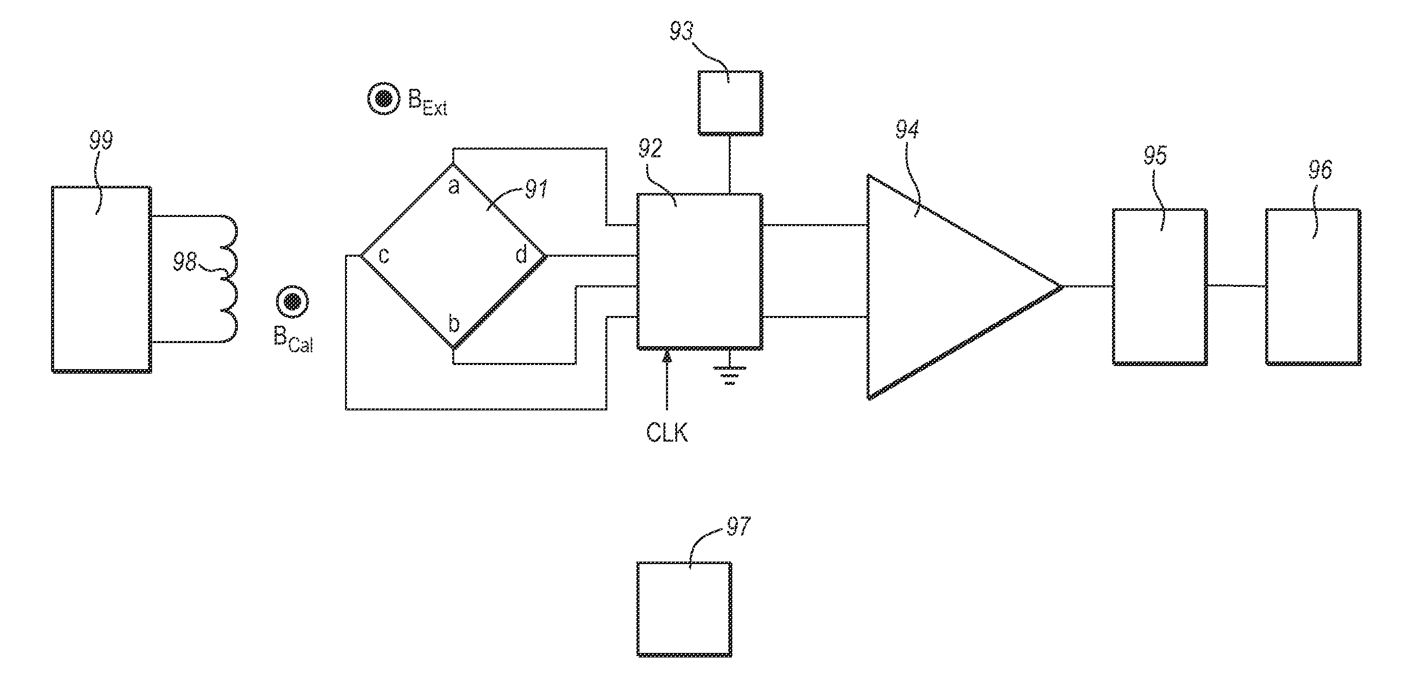
[0067]In a first phase, e.g. 0° phase, as illustrated in FIG. 3, a bias signal for biasing the Hall sensor is applied between a first set of two diagonally opposed electrodes a, c, e.g. a bias current IBias is applied between the electrodes a, c. The sensor signal VH is measured between Hi and Lo terminals connected to a second set of two diagonally opposed electrodes b, d.

[0068]The reference magnetic field BCal is generated by a magnetic field generator, e.g. a reference current ICal flowing through a coil, in the vicinity of the magnetic sensor device, e.g. Hall sensor, e.g. a coil surrounding the Hall plate.

[0069]The reference current ICal is kept constant in magnitude and direction during the ...

second embodiment

[0078]In a second embodiment, as illustrated in the time chart of FIG. 7, the reference or calibration magnetic field BCal is cancelled (magnitude is zero) during one of the two 90 degree sub-phases, e.g. during the second 90 degree sub-phase, rather than being inversed in direction while keeping the same amplitude. In the first of the two 90 degree sub-phases, in accordance with this embodiment, the reference current ICal keeps the magnitude and the direction it had during the 0 degree state. The resulting system of equations is:

VH1=SBExt+SBCal+Vop  (Eq. 6)

VH2=SBExt+SBCal−Vop  (Eq. 7)

VH3=SBExt−Vop  (Eq. 8)

[0079]The principal determinant of that system of equations on the unknowns x=S BExt, y=S BCal and z=Vop is:

[0080]11111-110-1 

which is equal to −2. Since that determinant is non zero, it guarantees that there exists one and only one solution for the three unknowns x=S BExt, y=S BCal and z=Vop satisfying the three equations Eq. 6, Eq. 7, and Eq. 8 simultaneously.

[0081]If the produc...

third embodiment

[0083]In a third embodiment, the first and second phases, e.g. 0 degree and 90 degree phases, are both divided into two sub-phases where the direction and / or the magnitude of the calibration field is changed (see for instance FIG. 8). The resulting values obtained for the product S BCal can be e.g. averaged to determine whether or not the sensitivity S has varied.

[0084]First the case is considered where the amplitude of the calibration field is kept constant but its direction is varied from one sub-phase to another and this for both the 0 degree and the 90 degree phases (see FIG. 8). Measurements of the output voltages VH1, VH2, VH3, VH4 are performed at time instants t1, t2, t3 and t4 in each of the sub-phases, respectively.

[0085]In that case, measuring the output voltages VH1, VH2, VH3, VH4 of the Hall sensor in each of the sub-phases will yield four linear equations. Contrary to what has been done in the above embodiments, it does not have to be assumed that the offset Vop is the...


PUM


Abstract

The present invention provides a method to compensate for the sensitivity drift of a magnetic field sensor for sensing a magnetic field. The magnetic field sensor comprises at least four electrodes. The method comprises a first step where a first set of two electrodes is used to bias the sensor and a second set of two electrodes is used to sense an output signal of the magnetic field sensor, and a second step where the second set of two electrodes is used to bias the sensor and the first set of two electrodes is used to sense an output signal of the magnetic field sensor. The method is characterized in that at least one of the first or the second step is subdivided in at least a first sub-step and a second sub-step. A reference magnetic field has first magnetic field parameters, e.g. a first amplitude and / or direction, in the first sub-step and second magnetic field parameters, a second amplitude and / or direction, in the second sub-step. An output signal is sensed in the first and in the second step, and within the first or the second step an output signal is sensed in the first and the second sub-step.

Description

CROSS-REFERENCE TO RELATED APPLICATIONS[0001]This patent application claims the benefit of British Patent Application Serial No. 0620307.9, filed Oct. 16, 2006, which patent application is incorporated herein by reference in its entirety.DESCRIPTION[0002]1. Field of the Invention[0003]The present invention proposes hardware and associated methods to eliminate the offset and the variation of sensitivity affecting magnetic sensors, e.g. integrated Hall sensors. The invention is also of application to other magnetic sensors for which an offset value can be isolated from an output value by using two phases that differ by the direction or the amplitude of a bias signal.[0004]2. Background of the Invention[0005]A Hall sensor for sensing magnetic fields is advantageously integrated in a semiconductor substrate. Such a sensor is typically a planar region of a semiconductor substrate, typically a square region of said substrate, also known as Hall plate, that is implanted with dopant impurit...

Claims


Application Information

Patent Timeline
Patent Type & Authority Patents(United States)
IPC IPC(8): G01R35/00
CPCG01R33/0017G01R33/0035G01R33/0206G01R33/07
Inventor CHARLIER, OLIVIERLAULANET, FRANCOISBADAROGLU, MUSTAFA
Owner AMI SEMICON BELGIUM
Why Eureka
Try Eureka