Method and system to increase X-Y resolution in a depth (Z) camera using red, blue, green (RGB) sensing

a depth camera and z-axis technology, applied in the field of images, can solve the problems of low resolution, low resolution, and inability to readily implement a large array, and achieve the goal of high resolution, high resolution, and easy operation.

Active Publication Date: 2012-03-13
MICROSOFT TECH LICENSING LLC
View PDF12 Cites 72 Cited by
  • Summary
  • Abstract
  • Description
  • Claims
  • Application Information

AI Technical Summary

Benefits of technology

[0019]In the various embodiments of the Ser. No. 11 / 044,996 application, incoming optical energy from a target object included wavelengths from both the first and second spectral bands (which bands could overlap), and preferably these wavelengths could include both RGB and preferably NIR components. In some embodiments, this energy was presented to at least one optical splitter that may be implemented as a wavelength-discriminating mirror, for example a hot mirror or a cold mirror. In other embodiments, a half-mirror (e.g., a mirror that reflects perhaps 40% to perhaps 60% of incoming optical energy) acted as the optical splitter. In these embodiments, the optical splitter operated passively to output an RGB image and a preferably NIR image. The RGB image could be focused upon an RGB pixel detector array, while the preferably NIR image could be focused upon a Z pixel detector array. Output from even a relatively low resolution pixel detector array that acquired Z data using preferably NIR wavelengths could be used to determine target object size, distance Z, target object velocity ΔZ / Δt. The Z data aided in rapidly identifying a target object imaged by the preferably RGB array.
[0021]According to the present invention, a low resolution z-image acquired from a first z-sensor array can rapidly determine the size and range of the object. But to determine the nature of the object, e.g., pedestrian or telephone pole, requires greater resolution, e.g., available from a second higher resolution RGB-sensor array. The present invention can render an RGBZ image using up-sampled z-image data, where the RGBZ image can have resolution equal to or even exceeding resolution of the second sensor array, from which image a user can readily identify objects, either as objects or avatars or icons. More specifically, according to the present invention, images are acquired using a first TOF z-sensor array (that acquires z-data and brightness data, albeit in relatively low resolution), and using second, high resolution, RGB sensor array. Frames of z-data and RGB-data are acquired substantially (but not necessarily exactly) simultaneously and are combined or “fused” to produce a single RGBZ frame of data of enhanced resolution. This fusion process results in higher z-resolution in the x-y plane, without having to provide a higher resolution first (z-sensor) array.
[0022]The fusion preferably is implemented with a fusion algorithm that seeks to take advantage of the different types of correlative or discrepant information provide by the first and second arrays. Preferably the fusion algorithm is substantially independent of whether mono or stereographic arrays are used. Fusion algorithms according to the present invention result in observably high accuracy with minimal registration overhead, and elimination of image correspondence problems so common with traditional approaches to depth-inference in the field of computer vision. A fusion algorithm according to the present invention provides for generality and extensibility, and can substantially reduce computational complexity. Preferably, time correlation of data captured from the first and second array is generalized by associating timing information with captured image data, e.g., by time-stamping captured frames of z-data and RGB data and enqueing in order of arrival. Preferably the algorithm enables association of image frames from the two arrays to take on an arbitrary mapping relationship. An effective sensor array providing z-resolution commensurate with, if not exceeding, resolution of a 1 MB z-sensor array can be implemented using a 1 MB RGB sensor array and a lower resolution z-sensor array.

Problems solved by technology

While such luminosity based sensors can provide a color (RGB) or gray scale (BW) image, they provide no useful depth information.
Unfortunately it is difficult to readily implement a large, high resolution array 55 because of the relatively large area required for the individual pixels, perhaps 50 μm·50 μm.
But this goal is difficult to attain in practice because, as noted above, pixel detectors used to capture Z-data at IR wavelengths are commonly much larger in area than pixel detectors responsive to RGB wavelengths, an area that is perhaps 100 times larger.
If a single detector array were fabricated to simultaneously use RGB pixel detectors and Z pixel detectors, the presence of the large sized Z pixel detectors in a high density array of much smaller sized RGB pixel detectors would cause large image artifacts that could degrade the quality of a resultant RGB image.
In practice, CMOS fabrication does not presently implement such bandpass filtering for the Z pixels, especially with desired narrow band characteristics that may be on the order of 50 nm or less.

Method used


Image

  • Method and system to increase X-Y resolution in a depth (Z) camera using red, blue, green (RGB) sensing
  • Method and system to increase X-Y resolution in a depth (Z) camera using red, blue, green (RGB) sensing
  • Method and system to increase X-Y resolution in a depth (Z) camera using red, blue, green (RGB) sensing

Examples


Embodiment Construction

[0046]Reference will now be made in detail to the preferred embodiments of the present invention, examples of which are illustrated in the accompanying drawings. While the present invention will be described in conjunction with the preferred embodiments, it will be understood that they are not intended to limit the invention to those embodiments. On the contrary, the invention is intended to cover alternatives, modifications and equivalents, which may be included within the spirit and scope of the invention as defined by the appended claims.

[0047]A description of the present invention commences with FIG. 8A. However it will be useful to appreciating the present invention to first review the invention of applicants's co-pending Ser. No. 11 / 044,996 application, which will now be described with reference to FIGS. 2-7.

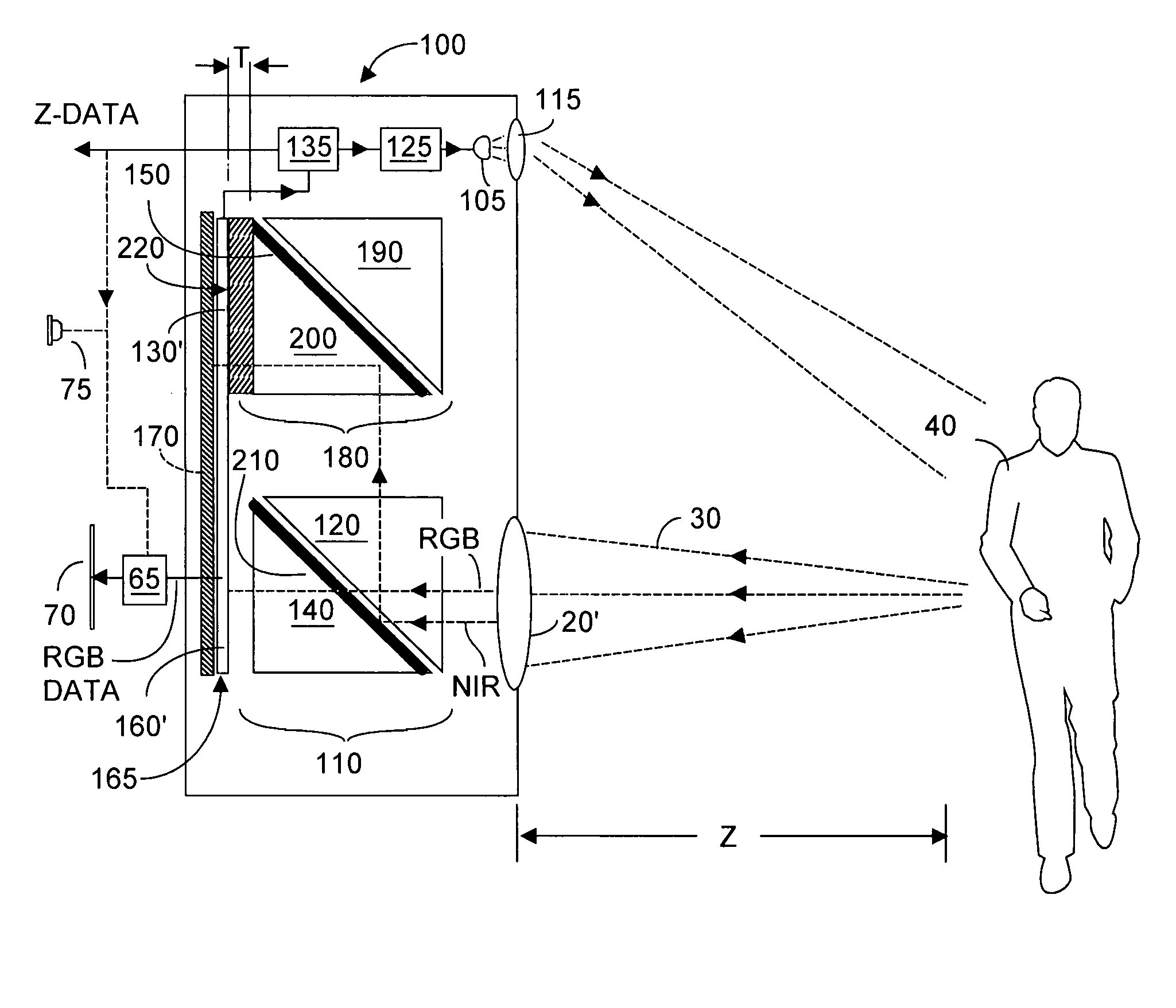
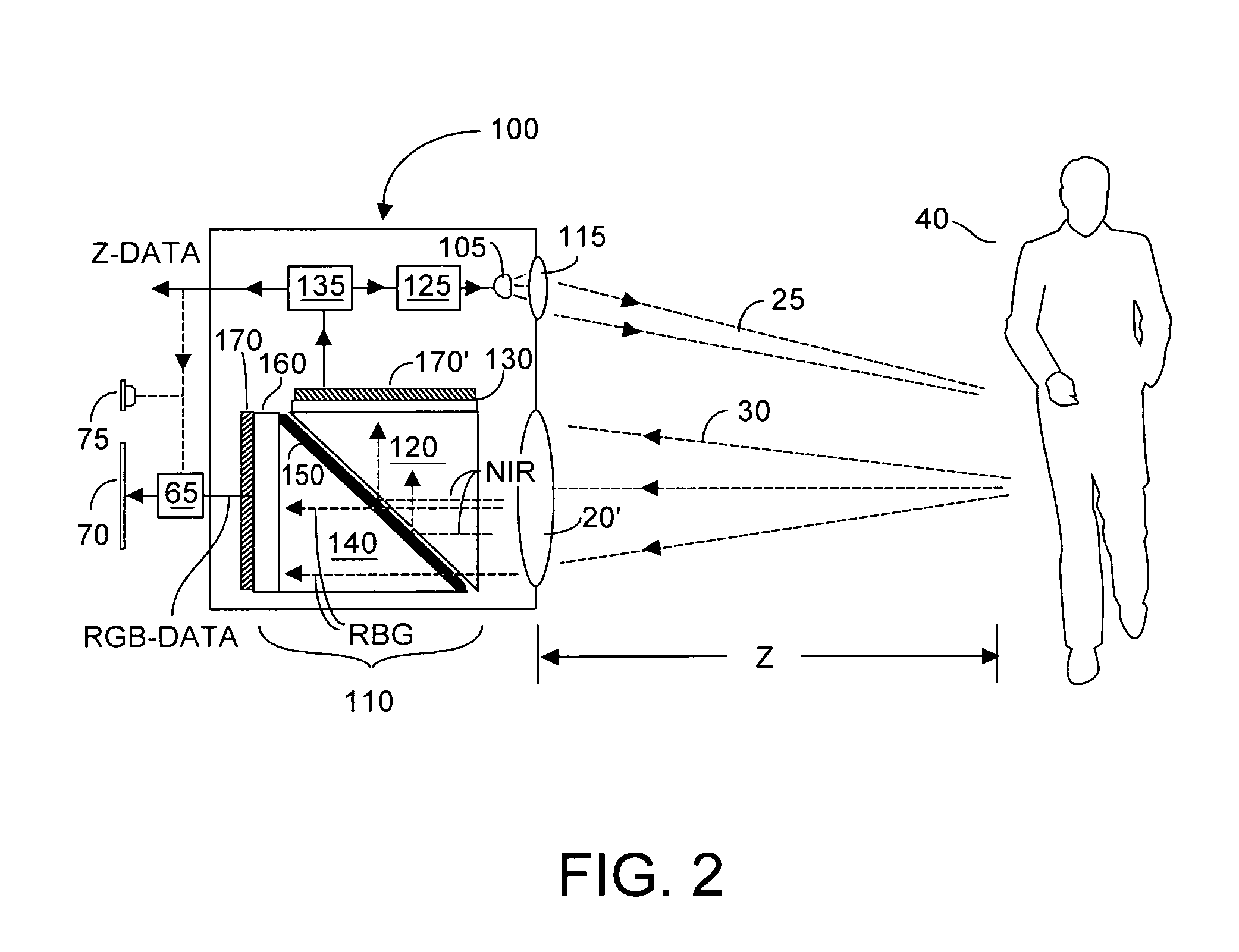
[0048]FIG. 2 depicts a camera system 100 that includes a preferably RGB-Z sensor 110, according to the Ser. No. 11 / 044,996 application. RGB-Z sensor 110 includes an array ...


PUM


Abstract

An imaging system substantially simultaneously acquires z-depth and brightness data from first sensors, and acquires higher resolution RGB data from second sensors, and fuses data from the first and second sensors to model an RGBZ image whose resolution can be as high as resolution of the second sensors. Time correlation of captured data from first and second sensors is associated with captured image data, which permits arbitrary mapping between the two data sources, ranging from 1:many to many:1. Preferably pixels from each set of sensors that image the same target point are mapped. Many z-depth sensor settings may be used to create a static environmental model. Non-correlative and correlative filtering is carried out, and up-sampling to increase z-resolution occurs, from which a three-dimensional model is constructed using registration and calibration data.

Description

CROSS-REFERENCE TO CO-PENDING RELATED APPLICATIONS[0001]This application claims priority to co-pending U.S. provisional patent application Ser. No. 60 / 686,470 filed 1 Jun. 2005 entitled RGBZ: Increasing X-Y Resolution of a Depth Camera Using an Ordinary Video Camera, and is also a continuation-in-part from co-pending U.S. patent application Ser. No. 11 / 044,996 filed 26 Jan. 2005 entitled Single Chip Red, Green, Blue, Distance (RGB-Z) Sensor, which application itself claimed priority from U.S. provisional patent application Ser. No. 60 / 540,523 filed 26 Jan. 2004 entitled Single Chip RGBZ Sensor.BACKGROUND OF THE INVENTION[0002]1. Field of the Invention[0003]The invention relates generally to images acquired with sensors (including sensors implementable on a single integrated circuit chip) responsive to luminosity information in a first spectral band (such as red, green, blue optical wavelengths, which shall be understood to include black and white) to acquire an red-green-blue (RGB) ...

Claims


Application Information

Patent Timeline
Patent Type & Authority Patents(United States)
IPC IPC(8): G03B13/00H04N5/225H04N9/07H04N13/02G01C3/08
CPCG01S17/89H04N5/2355H04N9/045H04N13/0022G01S17/936H04N13/128G01S17/931G01S17/894H04N23/741H04N23/84H04N25/135
Inventor ROSSBACH, CHRISTOPHER J.RAFII, ABBASZHAO, PEIQIAN
Owner MICROSOFT TECH LICENSING LLC
Why Eureka
Try Eureka