Imaging apparatus
a technology of imaging apparatus and r signal, which is applied in the direction of instruments, television systems, and color signal processing circuits, etc., can solve the problems of color image with high precision that cannot be produced, color reproducibility with fidelity cannot be achieved, and the frequency characteristics of r signal and b signal have not yet been improved, so as to achieve high resolution and color reproducibility. the effect of not deteriorating and high resolution
- Summary
- Abstract
- Description
- Claims
- Application Information
AI Technical Summary
Benefits of technology
Problems solved by technology
Method used
Image
Examples
first embodiment
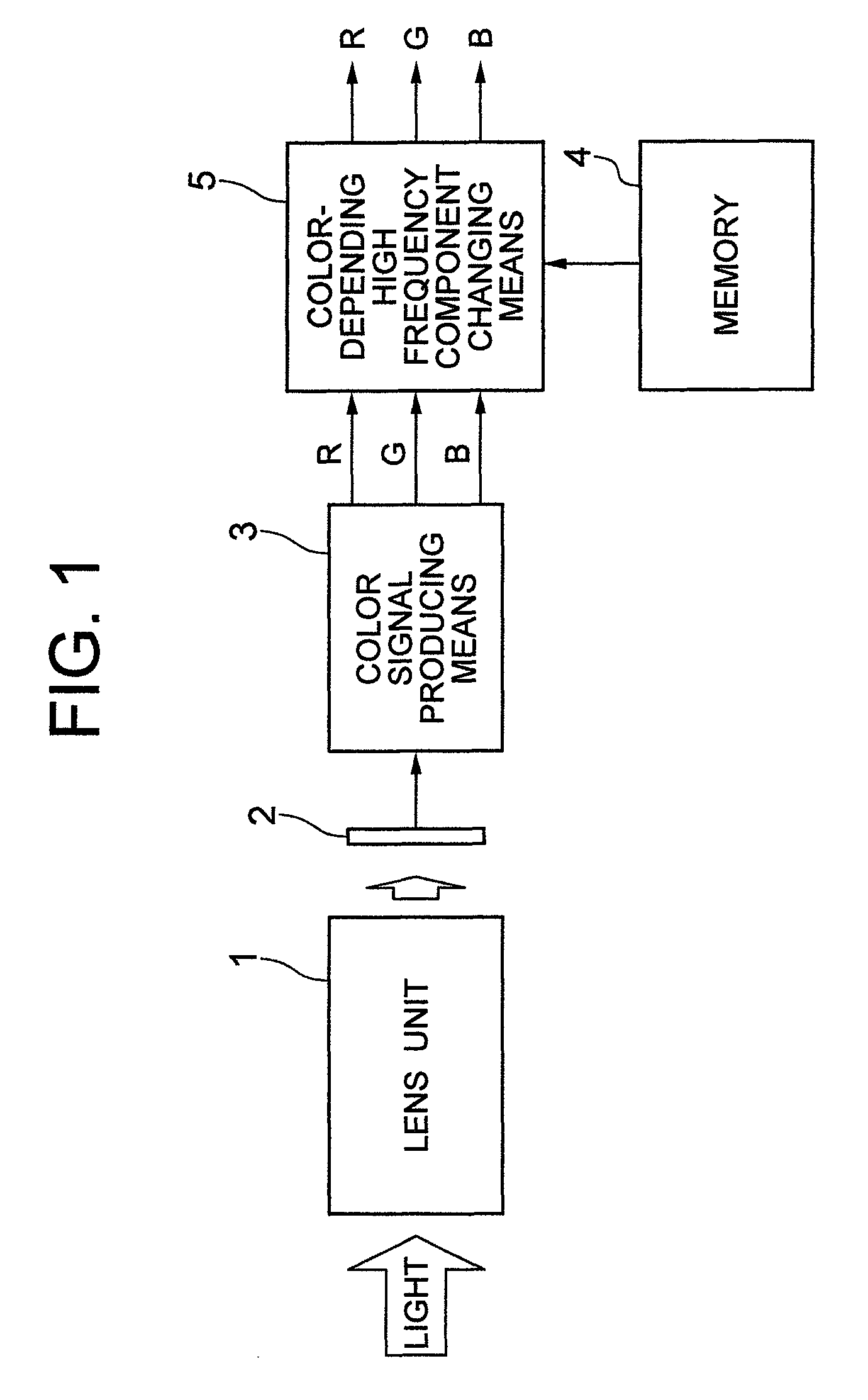
[0054]FIG. 1 is a structural diagram of an imaging apparatus according to the present invention. In the imaging apparatus of FIG. 1, reference numeral 1 shows a lens group (lens unit); reference numeral 2 indicates color imaging means; reference numeral 3 represents color signal producing means; reference numeral 4 shows a memory, and reference numeral 5 indicates color-depending high frequency component changing means.
[0055]In FIG. 1, while light is irradiated via the lens unit 1 onto the color imaging means 2, an image of a photographing object (not shown) is focused on an imaging plane (not shown) of the color imaging means (color imaging element) 2. The color imaging element 2 separates the above-described image of the photographing object every wavelength of the light in a spectral manner, and thereafter, photoelectrically converts the separated image light so as to output signals in response to the photographing object image. The color signal producing means 3 produces at leas...
second embodiment
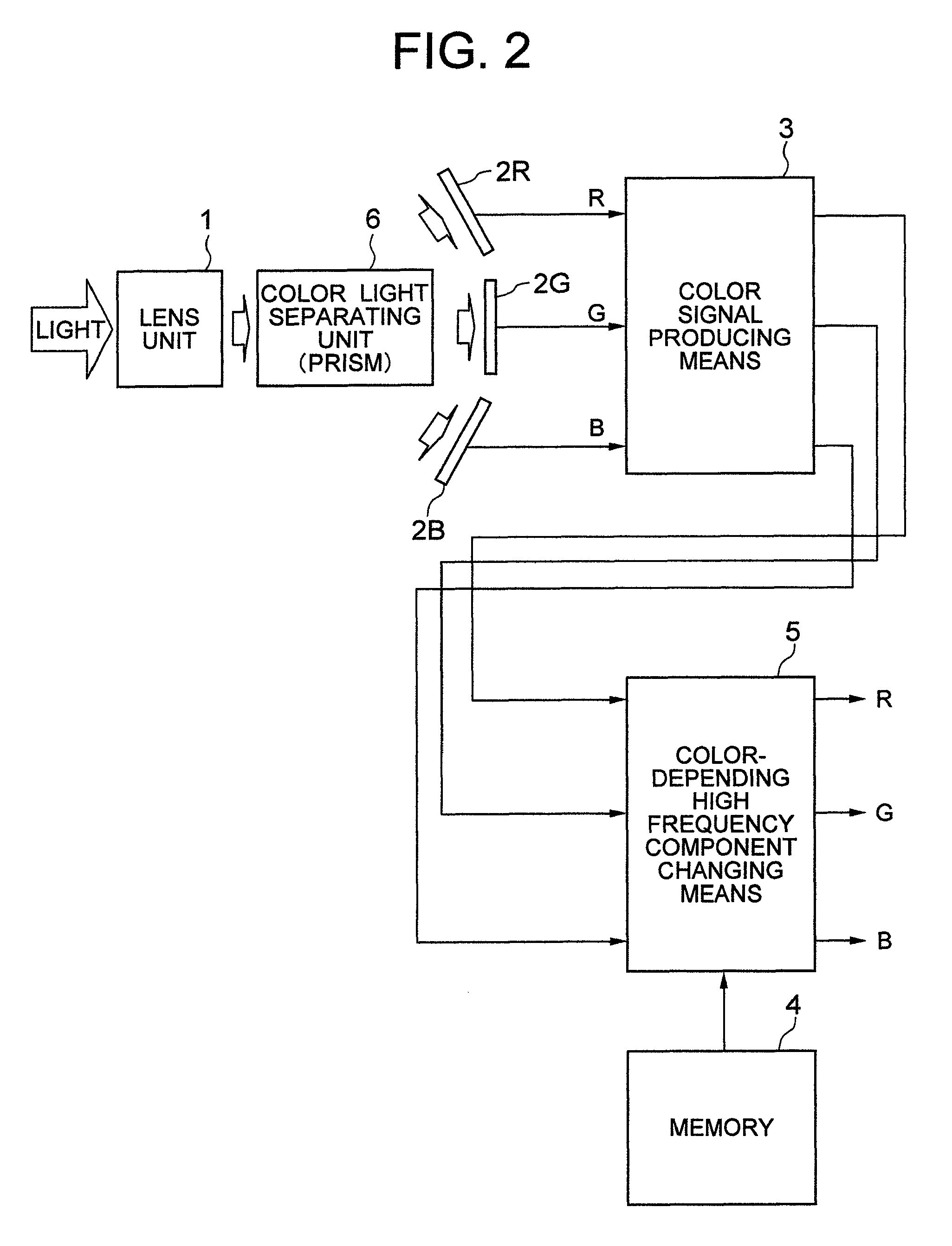
[0080]FIG. 5 is a block diagram for schematically showing a structure of an imaging apparatus according to the present invention. In FIG. 5, reference numeral 13 shows an iris; reference numeral 14 indicates a zoom lens; reference numeral 15 represents a focus lens; reference numeral 16 shows a zoom lens driving unit; reference numeral 17 indicates a focus lens driving unit; reference numeral 18 represents a focal length control unit; reference numeral 19 shows an optical zooming control unit; and reference numeral 20 indicates an iris control unit. It should be noted that the same reference numerals shown in FIG. 1 to FIG. 4 will be employed for denoting the same structural elements shown in FIG. 5, and therefore, the same descriptions thereof will be omitted.
[0081]In FIG. 5, light from a photographing object (not shown) is entered to a color imaging means 2 through the iris 13, the zoom lens 14, and the focus lens 15, which constitute a lens unit (lens group), and then, an image o...
third embodiment
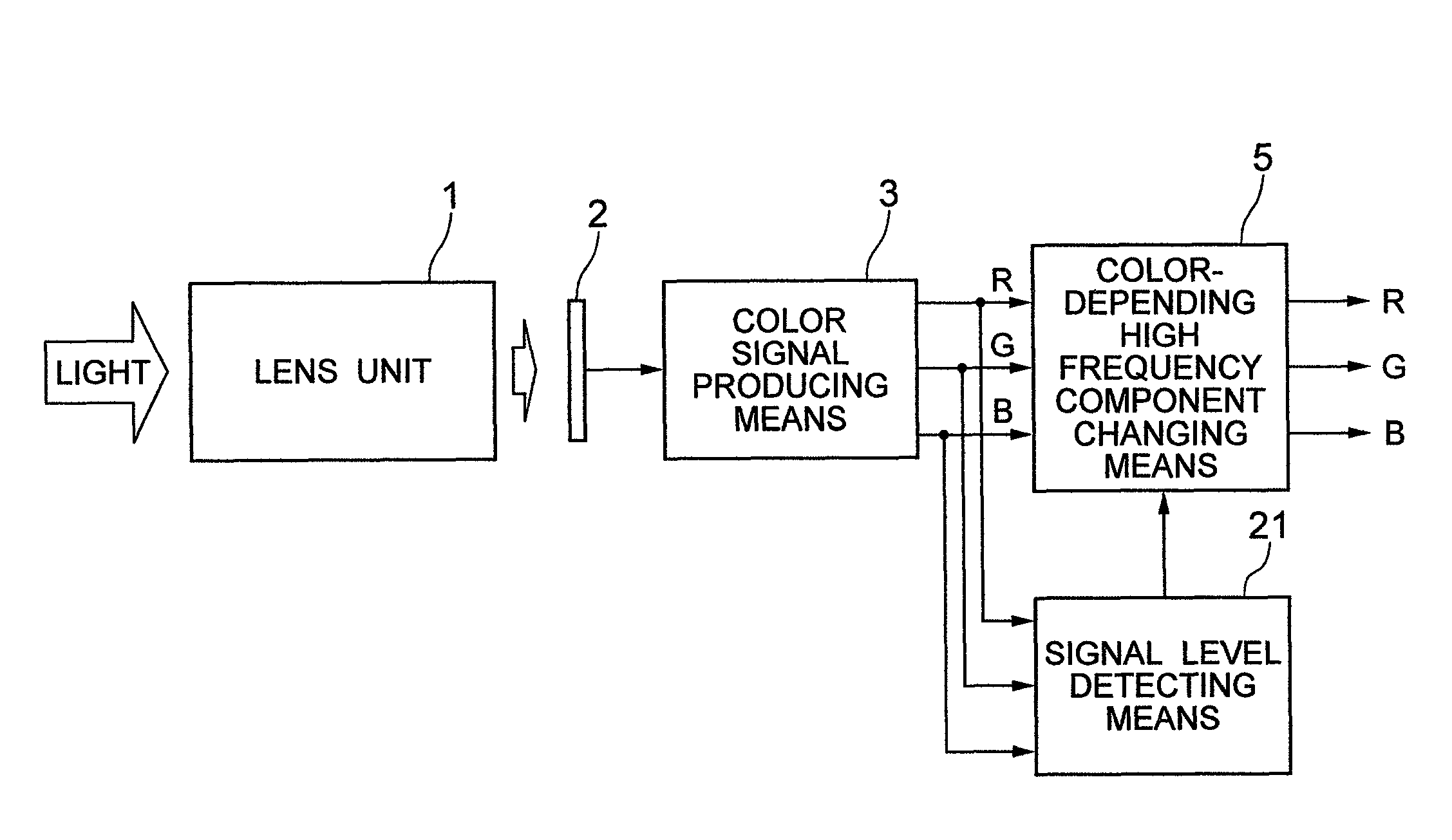
[0098]FIG. 6 is a block diagram for schematically showing a structure of an imaging apparatus according to the present invention. In FIG. 6, reference numeral 21 shows a signal level detecting means. It should be noted that the same reference numerals shown in FIG. 1 will be employed for denoting the same structural elements in FIG. 6, and therefore, the same descriptions thereof will be omitted.
[0099]In this drawing, R, G, B signals of 3 primary colors outputted from the color signal producing means 3 are supplied to the color-depending high frequency component changing means 5, and further, to the signal level detecting means 21.
[0100]The signal level detecting means 21 calculates each of averaged levels with respect to each of the R signal, the G signal, and the B signal. Also, the signal level detecting means 21 extracts high frequency components from the respective R, G, B color signals, and then, detects levels of these extracted high frequency components, and thereafter, calc...
PUM
 Abstract
Description
Claims
Application Information
 - R&D
- Intellectual Property
- Life Sciences
- Materials
- Tech Scout
- Unparalleled Data Quality
- Higher Quality Content
- 60% Fewer Hallucinations
Browse by: Latest US Patents, China's latest patents, Technical Efficacy Thesaurus, Application Domain, Technology Topic, Popular Technical Reports.
© 2025 PatSnap. All rights reserved.Legal|Privacy policy|Modern Slavery Act Transparency Statement|Sitemap|About US| Contact US: help@patsnap.com


