
Air cleaner for stratified-scavenging two-stroke internal combustion engine

a technology of air cleaner and internal combustion engine, which is applied in combustion-air/fuel-air treatment, liquid degasification, separation processes, etc., can solve the problems of increasing harmful elements (such as hc, co, etc.) in the exhaust gas discharged through the exhaust port of the cylinder port type two-stroke engine, and no valve mechanism dedicated to controlling the intake and exhaust functions

Active Publication Date: 2012-03-27
YAMABIKO CORP
View PDF10 Cites 4 Cited by
  • Summary
  • Abstract
  • Description
  • Claims
  • Application Information

AI Technical Summary

Benefits of technology

The present invention relates to an air cleaner for a stratified-scavenging two-stroke internal combustion engine used as a power source for portable power working machines. The invention addresses the problem of "blow-by" and "blow-back" in these engines, which can decrease fuel efficiency and increase harmful elements in the exhaust gas. The invention proposes a solution to these problems through the use of a stratified-scavenging design and an air-fuel mixture pre-compression technique. The invention also includes an air-fuel mixture passage and an air passage for efficient scavenging of the combustion chamber.

Problems solved by technology

That is, cylinder port type two-stroke engines have no valve mechanisms dedicated to controlling intake and exhaust functions.
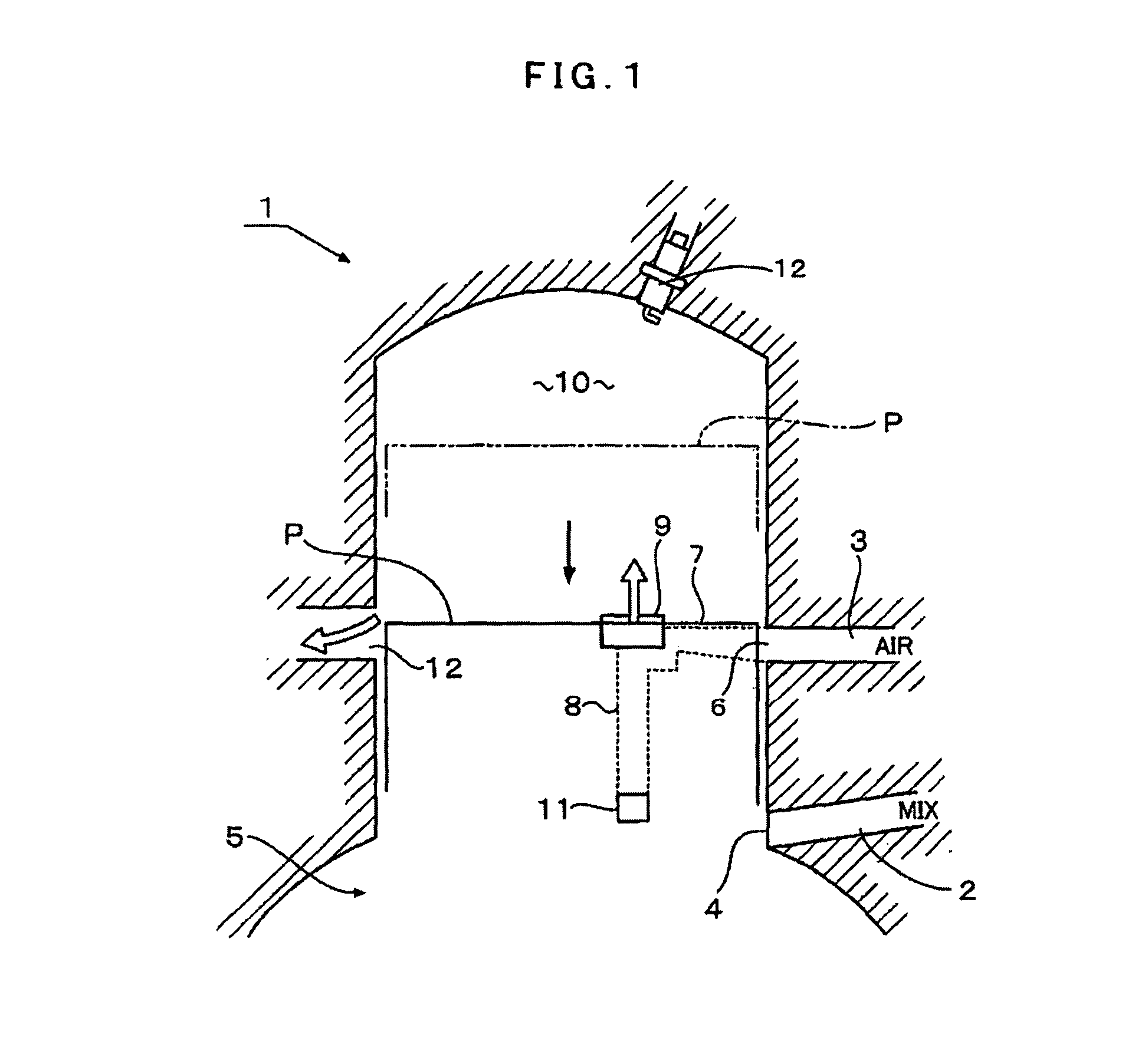
Because two-stroke internal combustion engines use fresh air-fuel mixture to scavenge the combustion chamber, they involve the problem of the so-called “blow-by” in which a part of fresh air-fuel mixture, not having burnt, is forced out together with the burnt gas.
Since the “blow-by” of air-fuel mixture is the phenomenon of undesired external discharge of fresh air-fuel mixture, it not only decreases the fuel efficiency but also increases harmful elements (such as HC, CO, etc.) in the exhaust gas discharged through the exhaust ports.
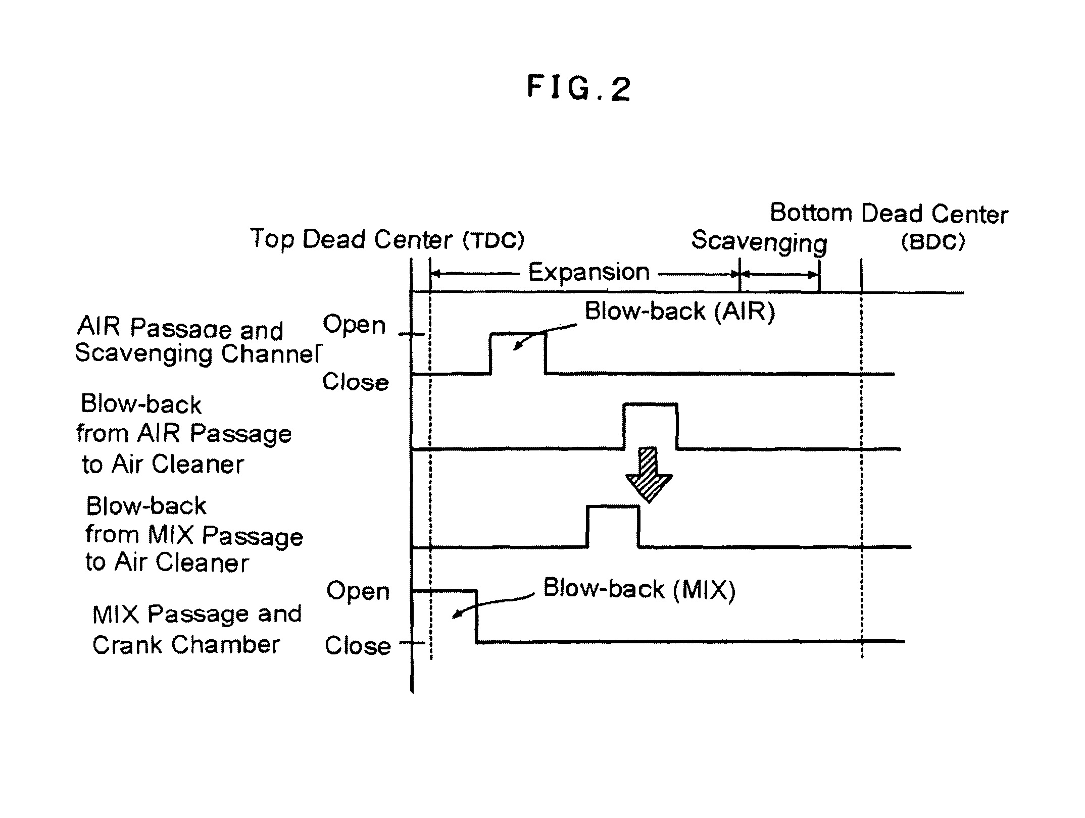
Two-stroke internal combustion engines involve the problem of “blow-back” in addition to the problem of “blow-by”.
Blow-back of air-fuel mixture becomes more notable as the engine revolution increases, and here occurs the problem that fuel components and oil components in the air-fuel mixture, which flows back down to an air cleaner, pollute the air cleaner elements.

Method used


Image

  • Air cleaner for stratified-scavenging two-stroke internal combustion engine
  • Air cleaner for stratified-scavenging two-stroke internal combustion engine
  • Air cleaner for stratified-scavenging two-stroke internal combustion engine

Examples


first embodiment

FIGS. 18 Through 24

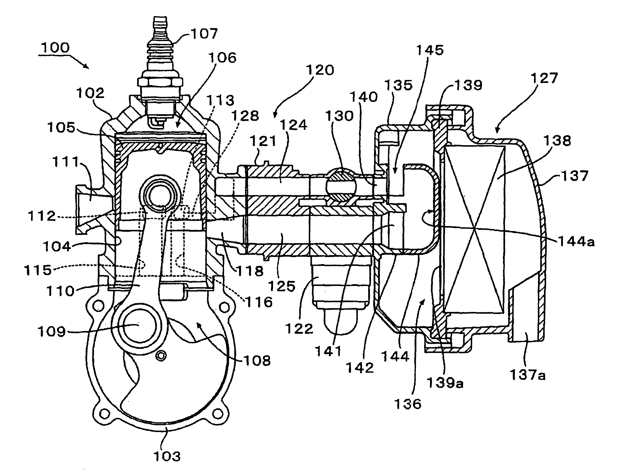
[0060]With reference to FIG. 18, a two-stroke internal combustion engine 100 is a gasoline engine fired by gasoline and an air-cooled engine having a single cylinder. This two-stroke gasoline engine 100 is a four-flow scavenging engine used in portable power working machines.

[0061]The engine 100 comprises a cylinder block 102 and a crankcase 103 connected under the cylinder block 102. A cylinder 104 formed in the cylinder block 102 fittingly, reciprocally accommodates a piston 105 that defines a combustion chamber 106 in the cylinder 104.

[0062]The combustion chamber 106 is of a squish dome design (hemispherical). At the top of the combustion chamber 106, an ignition plug 107 is located. The engine 100 further comprises a sealed crank chamber 108 defined by the crankcase 103.

[0063]The crank chamber 108 rotatably accommodates a crankshaft 109 supported on a pivot in the crankcase 103. The crankshaft 109 and the piston 105 are connected by a connection rod 110. Recip...

second embodiment

FIGS. 25 Through 32

[0080]The second embodiment is different from the first embodiment explained above only in the air cleaner 127, and common too the first embodiment in the other respects. Therefore, the following explanation is centered to differences from the first embodiment while omitting the common features by labeling them with common reference numerals.

[0081]The first air opening 140 in communication with the air passage 124 of the intake system 120 and the second air opening 141 in communication with the air-fuel mixture passage 125 are surrounded by the border uprising wall 142 like the first embodiment.

[0082]Unlike the first embodiment, the border uprising wall 142 has a uniform height over the entire circumference. As best shown in FIGS. 25 and 30, the guide member 150 used in the second embodiment has an elongated upside-down cup-shaped configuration. The first air opening 140 and the second air opening 141 are covered by the guide member 150 in a condition communicatin...

third embodiment

FIGS. 33 Through 40

[0087]The third embodiment is a modification of the second embodiment explained above. Its essential difference from the second embodiment lies in the shape of the guide member now labeled with 160. As best shown in FIG. 38, the guide member 160 used in the third embodiment has air induction tubes 161 corresponding to the air induction tubes 151 of the second embodiment. The air induction tubes 161 are oriented diagonal relative to the longer axis of the first air opening 140 having an elliptic configuration in its plan view, and extending directions of the air introduction tubes 161 orient toward the first air opening 140. Reference numeral 162 denotes an air induction channel defined by each air induction tube 161.

[0088]By diagonally orienting the air induction tubes 161, in the process where air is cleaned by the air cleaner element 138, then enters from the air induction tubes 161 into the space defined by the guide member 160 and is distributed to the first a...


PUM

PropertyMeasurementUnit
slanting angleaaaaaaaaaa
revolution speedaaaaaaaaaa
weightaaaaaaaaaa

Abstract

ObjectIt is intended to prevent intrusion of air-fuel mixture into an air cleaner by blow-back in an air-fuel mixture passage of a stratified-scavenging two-stroke engine.SolutionThe air cleaner (24) includes a guide member (30). A blow-back flow of air (20) flowing back to the air cleaner (24) through a first air opening (23A) due to blow-back of air is induced to a vicinity of a second air opening (23M) by the guide member (30). A blow-back flow of air-fuel mixture (21) occurring in an air-fuel mixture passage (2) prior to the blow-back phenomenon in an air passage (3) collides the air flow 20 moving toward the vicinity of the second air opening (23M), and retains the air-fuel mixture near the second air opening (23M).

Description

FIELD OF THE INVENTION[0001]The present invention relates to an air cleaner for a stratified-scavenging two-stroke internal combustion engine.BACKGROUND OF THE INVENTION[0002]Compact two-stroke internal combustion engines have been used as a power source of portable power working machines such as brush cutters, chain saws or the like. Two-stroke internal combustion engines used in portable power working machines are driven at a very high revolution speed as much as near 10,000 rpm or ten plus some thousands rpm in normal revolution.[0003]Compact two-stroke internal combustion engines generally have cylinder-port designs. In these two-stroke engines having such a cylinder-port design, air-fuel mixture ports and exhaust ports are formed in a sidewall of a cylinder, and opened or closed by a sidewall of a reciprocating piston. That is, cylinder port type two-stroke engines have no valve mechanisms dedicated to controlling intake and exhaust functions. Without complex valve mechanisms, ...

Claims


Application Information

Patent Timeline
Patent Type & Authority Patents(United States)
IPC IPC(8): F02B77/00
CPCF02M35/024F02M35/1017F02M35/1019F02M35/108F02B25/22F02B2075/025F02M35/02F02B25/14F02B63/02
Inventor TSUNODA, HIDEKAZU
Owner YAMABIKO CORP
Learn More