
Sound tuning method

a technology of sound tuning and sound, applied in the field of sound tuning, can solve the problems of high degree of experience, time-consuming, and system complexity, and achieve the effect of reducing the difficulty of tuning, and improving the accuracy of tuning

Active Publication Date: 2012-03-27
HARMAN BECKER AUTOMOTIVE SYST
View PDF11 Cites 14 Cited by
  • Summary
  • Abstract
  • Description
  • Claims
  • Application Information

AI Technical Summary

Benefits of technology

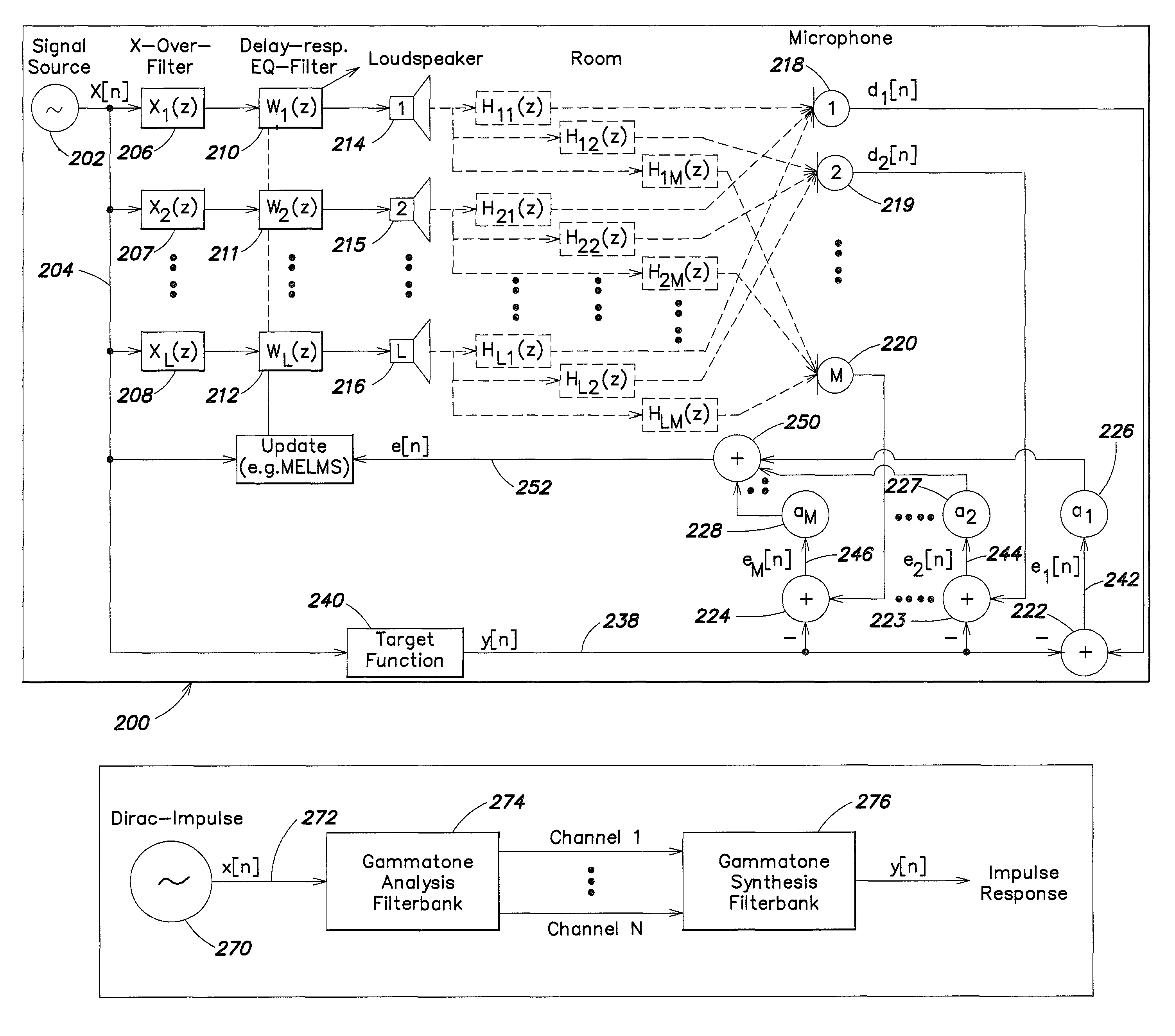
The invention is about a method and system for automatically tuning a sound system with delay lines, equalizing filters, and multiple loudspeakers. The method involves measuring sound pressure at different locations, adjusting the delay lines and equalizing filters to match a target transfer function that represents the desired sound system transfer characteristic. The system includes a signal source, adaptive filters, loudspeakers, and a microphone for measuring sound pressure levels. The control unit optimizes the filter coefficients to match the target function and ensure the actual transfer characteristics of the sound system approximates the desired transfer characteristic. The technical effects of the invention include improved sound quality, reduced distortion, and better overall listening experience.

Problems solved by technology

In motor vehicles, particularly in premium class vehicles, the sound systems are typically very complex and comprise a multiplicity of loudspeakers at the most varied positions in the passenger space of such vehicles, using loudspeakers and groups of loudspeakers for different frequency ranges (for example subwoofers, woofers, mid-frequency loudspeakers and tweeters, etc.).
However, a multiplicity of parameters have to be changed in this process that cannot be adjusted independently of one another and interact in their effect so that the procedure results in an iterative process which requires a high degree of experience, is correspondingly time-consuming and inevitably orientates itself largely around the subjective sound impression of the acoustician or sound engineer performing the tuning of the sound system.

Method used


Image

  • Sound tuning method
  • Sound tuning method
  • Sound tuning method

Examples


Embodiment Construction

[0037]In the present case, investigations have been conducted in order to determine first how acoustic parameters are changed when tuning is performed by trained acousticians or sound engineers. As a test environment, a premium class limousine has been selected. The sound system of this vehicle comprises a total of 10 channels (FrontLeft (LF), FrontRight (FR), Center (C), SideLeft (SL), SideRight (SR), RearLeft (RL), RearRight (RR), SubwooferLeft (SubL), SubwooferRight (SubR), a separate subwoofer (Sub)) located in the trunk and an amplifier for each channel. The tuning is performed using both phase tuning by changing the parameters of delay lines, all-pass filters and cross-over filters, and frequency tuning by changing the parameters of biquadratic, bilinear filters and cross-over filters. The separate subwoofer placed in the trunk of the vehicle is an active loudspeaker operated with a low-pass filter having a 100 Hz cut-off frequency, 90° phase shift, and volume set to the cente...


PUM


Abstract

The invention relates to a method for automated tuning of a sound system, the sound system comprising delay lines, equalizing filters, and at least two loudspeakers, the method comprising the steps of reproducing a useful sound signal through the loudspeakers, measuring sound pressure values at at least one location, providing a target transfer function for tuning the delay lines and the equalizing filters of the sound system, the target transfer function representing a desired transfer characteristics of the sound system, adjusting the delay of the delay lines, and adjusting amplitude responses of the equalizing filters such, that the actual transfer characteristics of the sound system approximates the target function.

Description

1. CLAIM OF PRIORITY[0001]This patent application claims priority to European Patent Application serial number 07 008 457.9 filed on Apr. 25, 2007.2. FIELD OF THE INVENTION[0002]The invention relates to sound tuning, and in particular to automated sound tuning or equalizing in passenger spaces of motor vehicles.3. RELATED ART[0003]In motor vehicles, particularly in premium class vehicles, the sound systems are typically very complex and comprise a multiplicity of loudspeakers at the most varied positions in the passenger space of such vehicles, using loudspeakers and groups of loudspeakers for different frequency ranges (for example subwoofers, woofers, mid-frequency loudspeakers and tweeters, etc.). Such sound systems are manually adjusted or optimized by acousticians or sound engineers for the respective vehicle type in order to achieve a desired sound impression. This process is also called sound tuning which is mainly tuning of the sound system and is subjectively performed by t...

Claims


Application Information

Patent Timeline
Patent Type & Authority Patents(United States)
IPC IPC(8): H03G3/20G10L15/00
CPCH03G3/32H03G5/005H03G9/005H04S7/301H04S7/307H04R2499/13H04R3/14H04S5/00
Inventor CHRISTOPH, MARKUSSCHOLZ, LEANDER
Owner HARMAN BECKER AUTOMOTIVE SYST
Learn More