Projector
a projector and projector technology, applied in the field of projectors, can solve the problems of color unevenness, difficult to completely correct the illuminance distribution, and deterioration of white balance, so as to prevent the decrease of illuminance and the relative invert of the illuminance distribution
- Summary
- Abstract
- Description
- Claims
- Application Information
AI Technical Summary
Benefits of technology
Problems solved by technology
Method used
Image
Examples
first embodiment
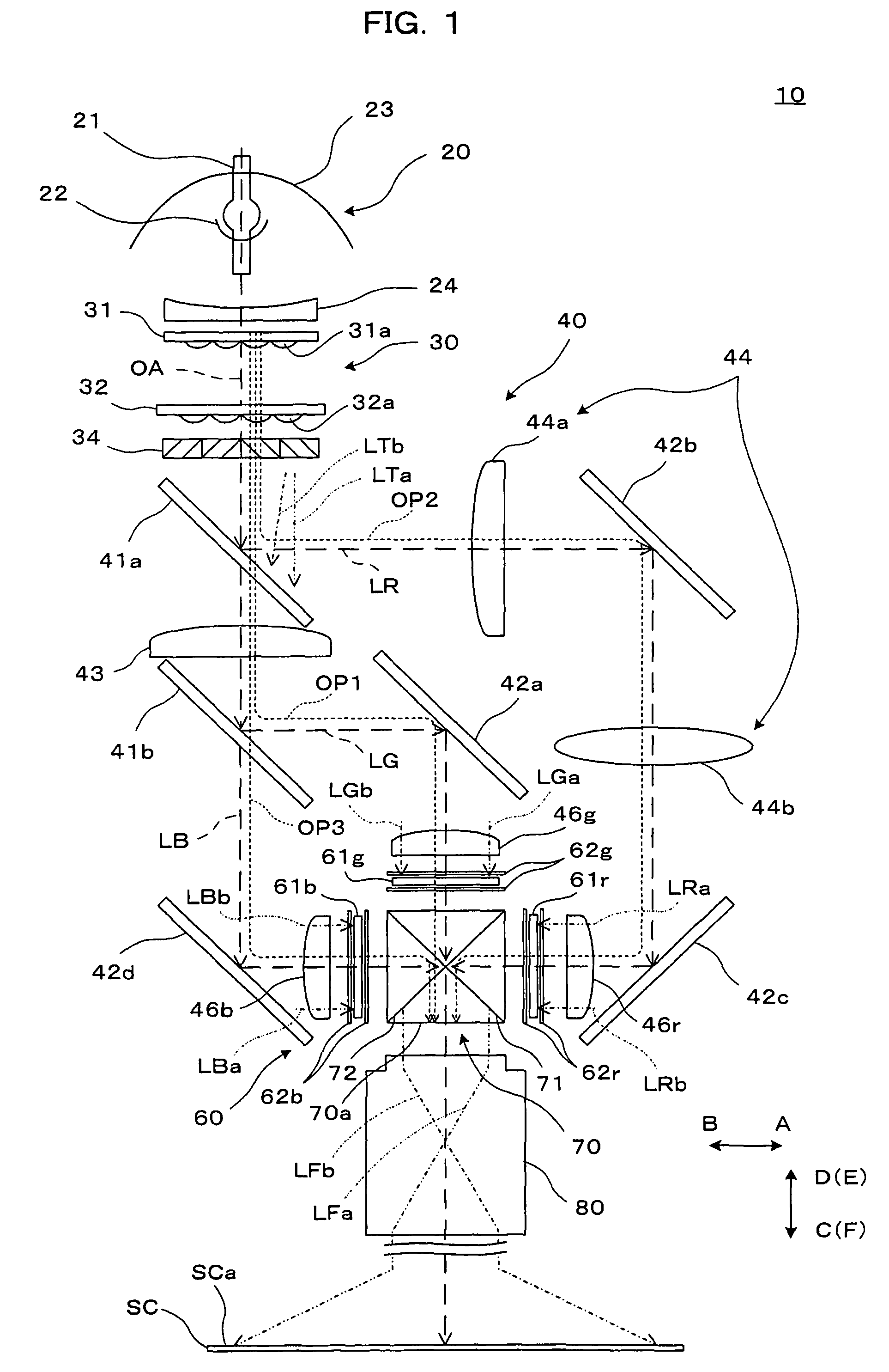
[0033]FIG. 1 illustrates a concept structure of optical systems of a projector according to a first embodiment of the invention.
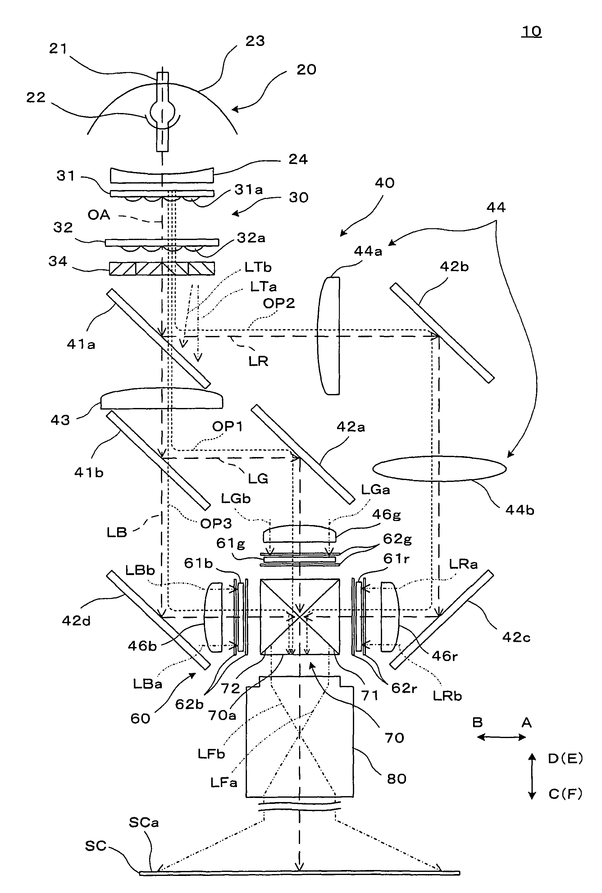
[0034]A projector 10 is an optical apparatus which forms color optical images by modulating light emitted from a light source according to image information and enlarges and projects the optical images on a screen SC. The projector 10 includes a light source lamp unit 20 as a light source, an illumination system 30, a color separation and light guide system 40, a light modulation unit 60, a cross dichroic prism 70, and a projection system 80. The light source lamp unit 20 and the illumination system 30 constitute a lighting device which produces illumination light to be supplied to the color separation and light guide system 40 and other units. First, second, and third optical paths OP1, OP2, and OP3 along which green light LG, red light LR, and blue light LB are guided are provided between the illumination system 30 and the cross dichroic prism 70.
[0035]Th...
second embodiment
[0058]A projector according to a second embodiment of the invention is now described. The projector in the second embodiment is a projector produced by partially modifying the projector in the first embodiment, and similar components are not particularly explained herein.
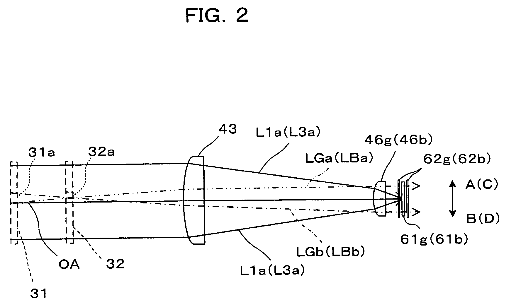
[0059]FIG. 4 corresponds to FIG. 3, showing a condition of light on the second optical path OP2 of the projector 10 according to the second embodiment. The second superimposing lens 44 constituted by one lens is disposed on the second optical path OP2 of the projector 10 in this embodiment. FIG. 4 shows a condition of light on a linear optical path from which reflection by the second dichroic mirror 41b and the reflection mirrors 42b and 42c on the second optical path OP2 is removed in place of the optical path OP2. Thus, the figure shows a virtual condition of a linear optical path having no reflection surface in place of the second optical path OP2.
[0060]On the second optical path OP2 in this embodiment, the red b...
third embodiment
[0062]A projector according to a third embodiment of the invention is now described. The projector in the third embodiment is a projector produced by partially modifying the projector in the first embodiment, and similar components are not particularly explained herein.
[0063]FIG. 5 illustrates a concept of a structure of optical systems included in a projector 110 according to a third embodiment. The projector 110 in this embodiment includes the light source lamp unit 20, an illumination system 130, a color separation and light guide system 140, the light modulation unit 60, the cross dichroic prism 70, and the projection system 80.
[0064]The illumination system 130 is an optical system which divides light emitted from the light source lamp unit 20 into a plurality of partial lights and converts illumination light into polarized light in a specific direction, and has the first multi-lens 31, the second multi-lens 32, the polarization converting device 34, and the first and second sup...
PUM
| Property | Measurement | Unit |
|---|---|---|
| length | aaaaa | aaaaa |
| area | aaaaa | aaaaa |
| reflection | aaaaa | aaaaa |
Abstract
Description
Claims
Application Information
 - R&D
- Intellectual Property
- Life Sciences
- Materials
- Tech Scout
- Unparalleled Data Quality
- Higher Quality Content
- 60% Fewer Hallucinations
Browse by: Latest US Patents, China's latest patents, Technical Efficacy Thesaurus, Application Domain, Technology Topic, Popular Technical Reports.
© 2025 PatSnap. All rights reserved.Legal|Privacy policy|Modern Slavery Act Transparency Statement|Sitemap|About US| Contact US: help@patsnap.com


