Projector

Active Publication Date: 2009-08-06
SEIKO EPSON CORP
View PDF21 Cites 2 Cited by
  • Summary
  • Abstract
  • Description
  • Claims
  • Application Information

AI Technical Summary

Benefits of technology

[0008]Accordingly, it is an object of the invention to provide a projector which includes simplified optic

Problems solved by technology

When the relative illuminance distributions of lights applied to the respective liquid crystal light valves are different in the projector having the above structure, deterioration of white balance, color unevenness or the like of the projection image obtained by combination of the lights is caused

Method used


Image

  • Projector
  • Projector
  • Projector

Examples


first embodiment

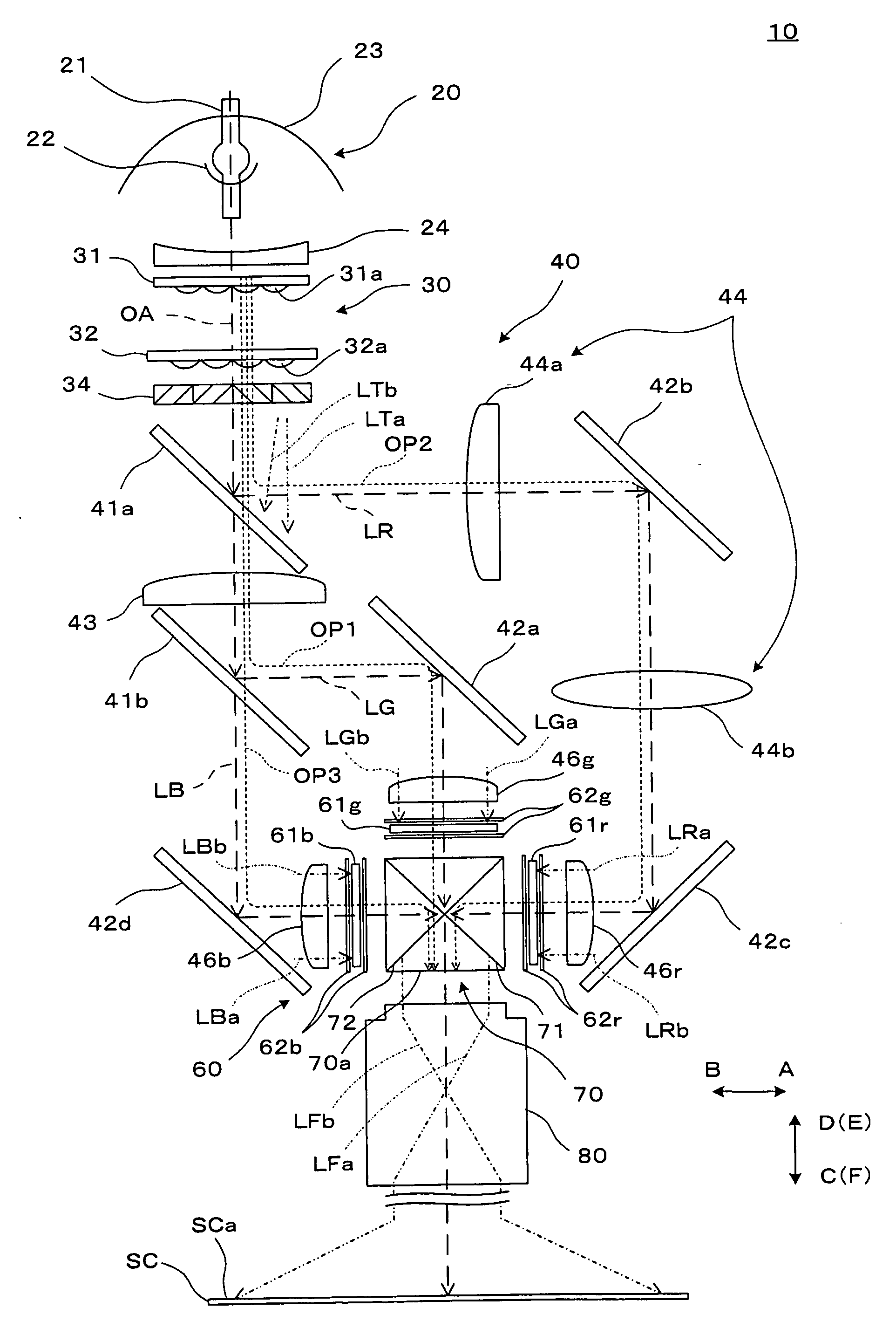
[0033]FIG. 1 illustrates a concept structure of optical systems of a projector according to a first embodiment of the invention.

[0034]A projector 10 is an optical apparatus which forms color optical images by modulating light emitted from a light source according to image information and enlarges and projects the optical images on a screen SC. The projector 10 includes a light source lamp unit 20 as a light source, an illumination system 30, a color separation and light guide system 40, a light modulation unit 60, a cross dichroic prism 70, and a projection system 80. The light source lamp unit 20 and the illumination system 30 constitute a lighting device which produces illumination light to be supplied to the color separation and light guide system 40 and other units. First, second, and third optical paths OP1, OP2, and OP3 along which green light LG, red light LR, and blue light LB are guided are provided between the illumination system 30 and the cross dichroic prism 70.

[0035]Th...

second embodiment

[0058]A projector according to a second embodiment of the invention is now described. The projector in the second embodiment is a projector produced by partially modifying the projector in the first embodiment, and similar components are not particularly explained herein.

[0059]FIG. 4 corresponds to FIG. 3, showing a condition of light on the second optical path OP2 of the projector 10 according to the second embodiment. The second superimposing lens 44 constituted by one lens is disposed on the second optical path OP2 of the projector 10 in this embodiment. FIG. 4 shows a condition of light on a linear optical path from which reflection by the second dichroic mirror 41b and the reflection mirrors 42b and 42c on the second optical path OP2 is removed in place of the optical path OP2. Thus, the figure shows a virtual condition of a linear optical path having no reflection surface in place of the second optical path OP2.

[0060]On the second optical path OP2 in this embodiment, the red b...

third embodiment

[0062]A projector according to a third embodiment of the invention is now described. The projector in the third embodiment is a projector produced by partially modifying the projector in the first embodiment, and similar components are not particularly explained herein.

[0063]FIG. 5 illustrates a concept of a structure of optical systems included in a projector 110 according to a third embodiment. The projector 110 in this embodiment includes the light source lamp unit 20, an illumination system 130, a color separation and light guide system 140, the light modulation unit 60, the cross dichroic prism 70, and the projection system 80.

[0064]The illumination system 130 is an optical system which divides light emitted from the light source lamp unit 20 into a plurality of partial lights and converts illumination light into polarized light in a specific direction, and has the first multi-lens 31, the second multi-lens 32, the polarization converting device 34, and the first and second sup...


PUM


Abstract

A projector can form images of illumination system on respective optical paths at positions of corresponding liquid crystal display panels with respect to a light emission surface of a cross dichroic prism without relatively inverting the images and without increasing the number of lenses from the number of lenses included in a relay optical path structure in related art. Moreover, the projector can equalize the magnification of the images formed on the respective liquid crystal display panels by controlling relative image-forming conditions of the first and second optical paths in advance. Thus, deterioration of white balance and color unevenness of light projected by the projector can be reduced even when light emission distribution of a light source varies with elapse of time, for example.

Description

BACKGROUND OF THE INVENTION[0001]1. Technical Field[0002]The present invention relates to a projector which modulates illumination light by using a light modulation device and projects modulated image light.[0003]2. Description of Related Art[0004]A typical known projector includes a light source which emits approximately white light, an illumination system which equalizes light emitted from the light source and converts the light into polarized light, a color separation and light guide system which separates the light having passed the illumination system and guides the light along optical paths for three color lights in green, blue, and red, three liquid crystal light valves illuminated by the illumination lights in three colors, a cross dichroic prism which combines images received from the three liquid crystal light valves, and a projection lens which enlarges the combined image and projects the enlarged image.[0005]When the relative illuminance distributions of lights applied t...

Claims


Application Information

Patent Timeline
IPC IPC(8): G03B21/14
CPCG03B33/06G03B33/12H04N9/3197H04N9/315H04N9/3105G03B21/2066G03B21/208
Inventor SAKAI, KENSHI
Owner SEIKO EPSON CORP
Why Eureka
Try Eureka