
Device for thermally treating at least one optical fibre

a technology of thermal treatment and optical waveguide, which is applied in the direction of optical elements, manufacturing tools, instruments, etc., can solve the problems of splice quality, temperature gradient between, and incomplete welding of the two ends of optical waveguides

Inactive Publication Date: 2006-07-13
CORNING CABLE SYST LLC +1
View PDF4 Cites 0 Cited by
  • Summary
  • Abstract
  • Description
  • Claims
  • Application Information

AI Technical Summary

Benefits of technology

The present invention is a device for thermally treating optical waveguides, which allows for uniform heating without the need for a large focal length mirror or frequent cleaning. The device uses a first optical system to generate a beam profile with a symmetrical power density profile, and a second optical system to reflect and direct the beam onto the waveguide from both sides. This results in a heating that is more uniform and symmetrical, improving the quality of the spliced connection. The device can be used for splicing multiple optical waveguides and is suitable for splicing optical waveguides in a simple and efficient manner.

Problems solved by technology

A problem when using a laser beam as the heat source is that when the laser beam strikes the optical waveguide on one side, a temperature gradient is produced between the side facing the laser beam and the side of the optical waveguides facing away from the laser beam.
This may result in an asymmetry of the splice which can lead to incomplete welding of the two ends of the optical waveguides.
The splice quality, characterized in particular by the coupling losses which occur and the tensile strength of the splice, is generally worsened when heat is applied on one side.
The disadvantage of this solution is that when the splicing time is increased the heating zone is also made larger.
The disadvantage with this solution is that when the mirror has a large focal length the mounts of the two fibers are located in the optical beam path and they in turn give rise to shading and thus to unequal heating.

Method used


Image

  • Device for thermally treating at least one optical fibre
  • Device for thermally treating at least one optical fibre
  • Device for thermally treating at least one optical fibre

Examples


Embodiment Construction

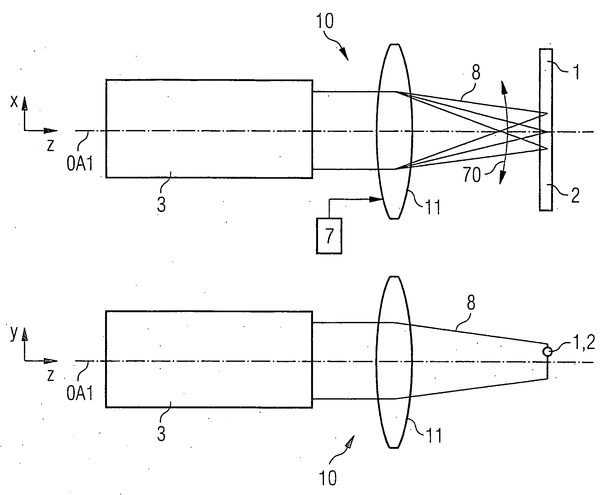
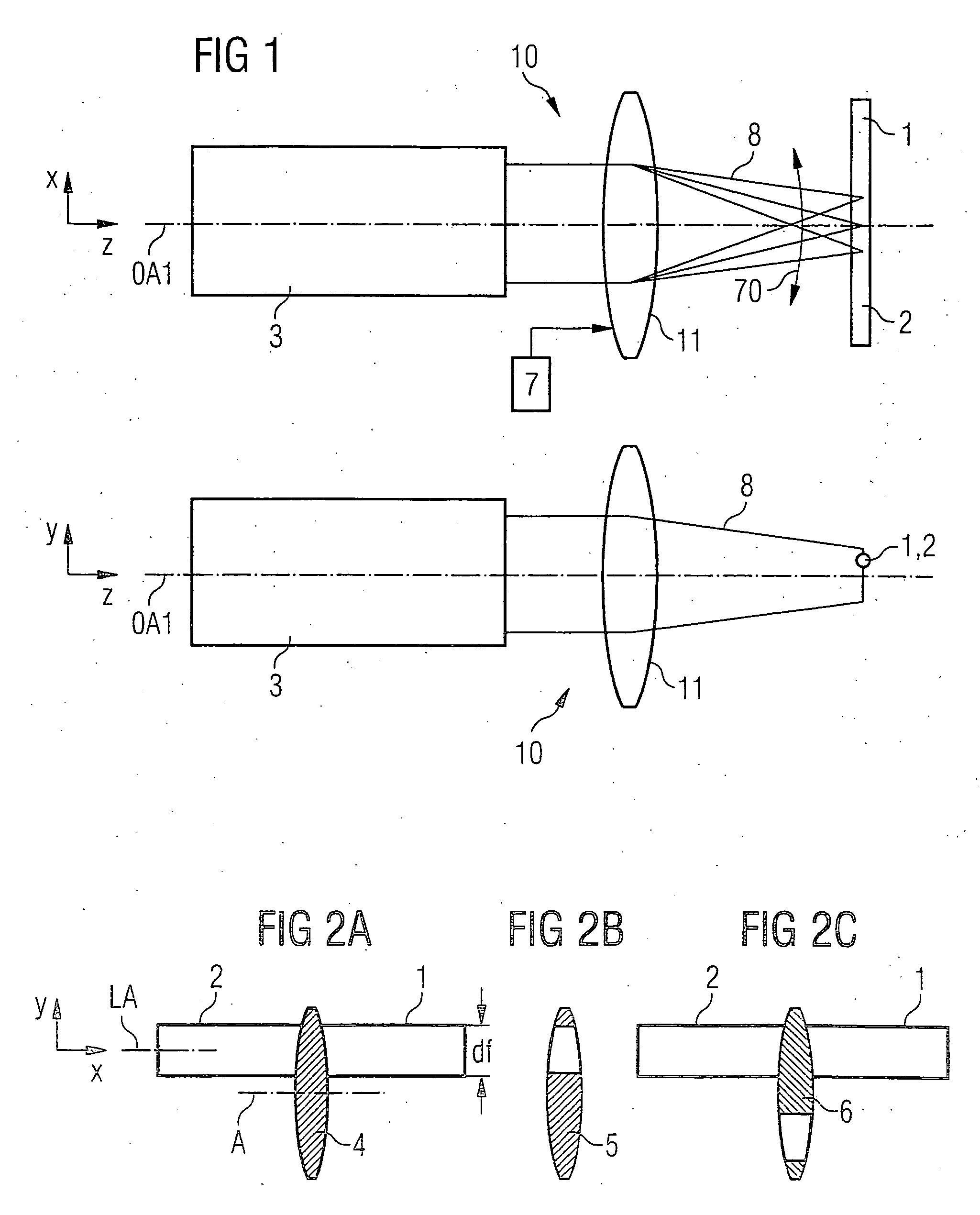
[0026]FIG. 1 shows a schematic illustration of an embodiment of the device according to the invention. A laser beam source 3 and a first optical system 10 for directing and preferably focusing a laser beam 8 emitted by the laser beam source onto the optical waveguide fibers 1 and 2 are represented. The first optical system 10 also includes the radiation optics of the laser for directing the laser beam.

[0027]FIG. 1 shows by way of example the imaging of the laser beam 8 onto the fibers to be spliced from two orthogonal directions. In the direction along the longitudinal axes of the fibers 1, 2, the laser beam 8 can be shifted in the longitudinal direction thereof, in particular moved periodically (movement direction 70 of the laser radiation 8). This uses a schematically illustrated drive device 7, which moves an optical component in the form of a lens 11 in such a way that a position of a focusing area of the laser beam inside which the radiation strikes the optical waveguide fiber...


PUM

PropertyMeasurementUnit
diameteraaaaaaaaaa
focal lengthsaaaaaaaaaa
focal lengthaaaaaaaaaa

Abstract

A device for thermally treating at least one optical waveguide has a radiation source. A first optical system is used to direct a beam, emitted by the radiation source, onto the optical waveguide from a first side. The first optical system generates a beam profile whose extent in the transverse direction with respect to a longitudinal axis of the optical waveguide corresponds to at least twice an optical waveguide diameter. The optical waveguide is positioned completely outside a center axis of the beam profile in the transverse direction with respect to the longitudinal axis of the optical waveguide in the focusing area of the beam. A second optical system which is positioned behind the optical waveguide in the direction of a beam path of the beam, reflects and directs a beam, which is transmitted past the side of the optical waveguide, onto the optical waveguide from a second side.

Description

[0001] This National stage application claims the benefit of International Application No. PCT / DE03 / 03630, filed on Oct. 31, 2003, which claims the benefit of German Patent Application No. 10250880.1, filed on Oct. 31, 2002, and which was not published in the English language under PCT Article 21(2).FIELD OF THE INVENTION [0002] The present invention relates to a device for thermally treating at least one optical waveguide having a radiation source and having an optical system for directing a beam, emitted by the radiation source, onto the optical waveguide. BACKGROUND OF THE INVENTION [0003] In a method for thermally splicing optical waveguides, glass fibers which are to be connected are generally heated to melting temperature by a heat source and placed in contact. Contemporary splicing devices generally use an electric glow discharge as an energy source for the splicing process. It is also possible to use a laser, preferably a CO2 laser, as a heat source, said laser providing the...

Claims


Application Information

Patent Timeline
Patent Type & Authority Applications(United States)
IPC IPC(8): G02B6/00B23K26/073G02B6/255G02B6/38
CPCB23K26/0736G02B6/2551G02B6/2553
Inventor CONTAG, KARSTEN
Owner CORNING CABLE SYST LLC
Learn More