Reference current generating circuit

a current generation circuit and reference technology, applied in the direction of digital storage, process and machine control, instruments, etc., can solve the problems of deteriorating semiconductor device characteristics, failure to read out an off-cell, and reducing the current of the field effect transistor

Inactive Publication Date: 2012-04-03
KK TOSHIBA
View PDF13 Cites 48 Cited by
  • Summary
  • Abstract
  • Description
  • Claims
  • Application Information

AI Technical Summary

Problems solved by technology

As a result of the increased threshold voltage Vth of the field effect transistor, the current of the field effect transistor is decreased and the characteristics of the semiconductor device are deteriorated.
As a result, the value of the standard current at EOL may be within the range of the off-cell current distribution, thereby causing a malfunction in reading out an off-cell.
This leads to a problem that if the widths of the on-cell and the off-cell current distributions are increased, it becomes difficult to adjust the reference level within the intermediate range between the lower limit of the on-cell current distribution and the upper limit of the off-cell current distribution.

Method used


Image

  • Reference current generating circuit
  • Reference current generating circuit
  • Reference current generating circuit

Examples


first embodiment

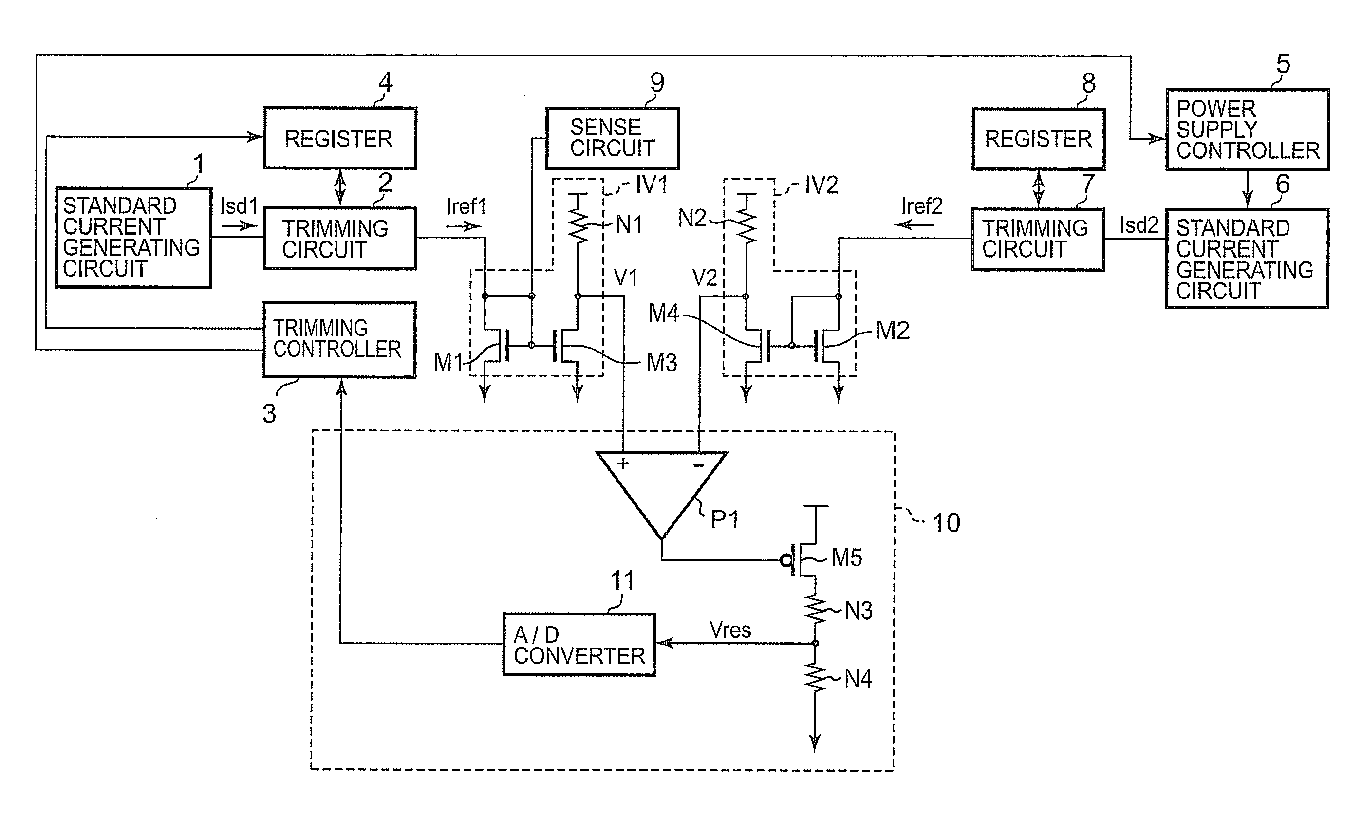
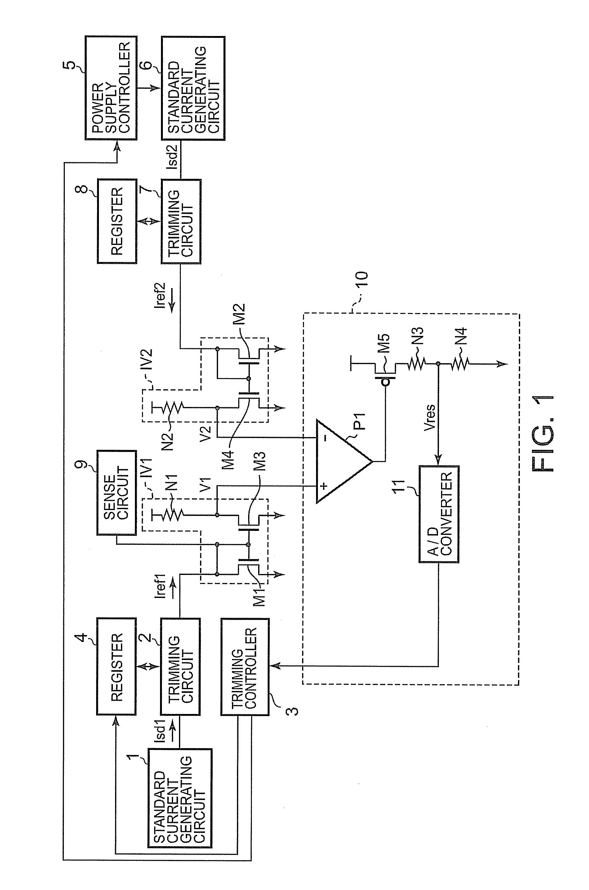
[0020]FIG. 1 is a block diagram schematically showing a structure of a reference current generating circuit according to a first embodiment of the invention. In FIG. 1, the reference current generating circuit includes first and second standard current generating circuits 1, 6, first and second trimming circuits 2, 7, a trimming controller 3, first and second registers 4, 8, a power supply controller 5, a comparison circuit 10, and first and second current / voltage conversion circuits IV1, IV2.

[0021]Here, the first standard current generating circuit 1 generates a standard current Isd1. The second standard current generating circuit 6 generates a standard current Isd2. The second standard current generating circuit 6 operates for a part of the operation period of the first standard current generating circuit 1. The first standard current generating circuit 1 always operates, and the second standard current generating circuit 6 operates periodically for only a predetermined period of ...

second embodiment

[0077]FIG. 5 is a block diagram schematically showing a structure of a reference current generating circuit according to a second embodiment of the invention.

[0078]In addition to the structure of the reference current generating circuit in FIG. 1, the reference current generating circuit in FIG. 5 includes an error correction circuit 31 and an error frequency determiner 32. The error correction circuit 31 corrects error data read from the memory cell MC in FIG. 2. The error frequency determiner 32 determines an error frequency on the basis of a result of a correction performed by the error correction circuit 31.

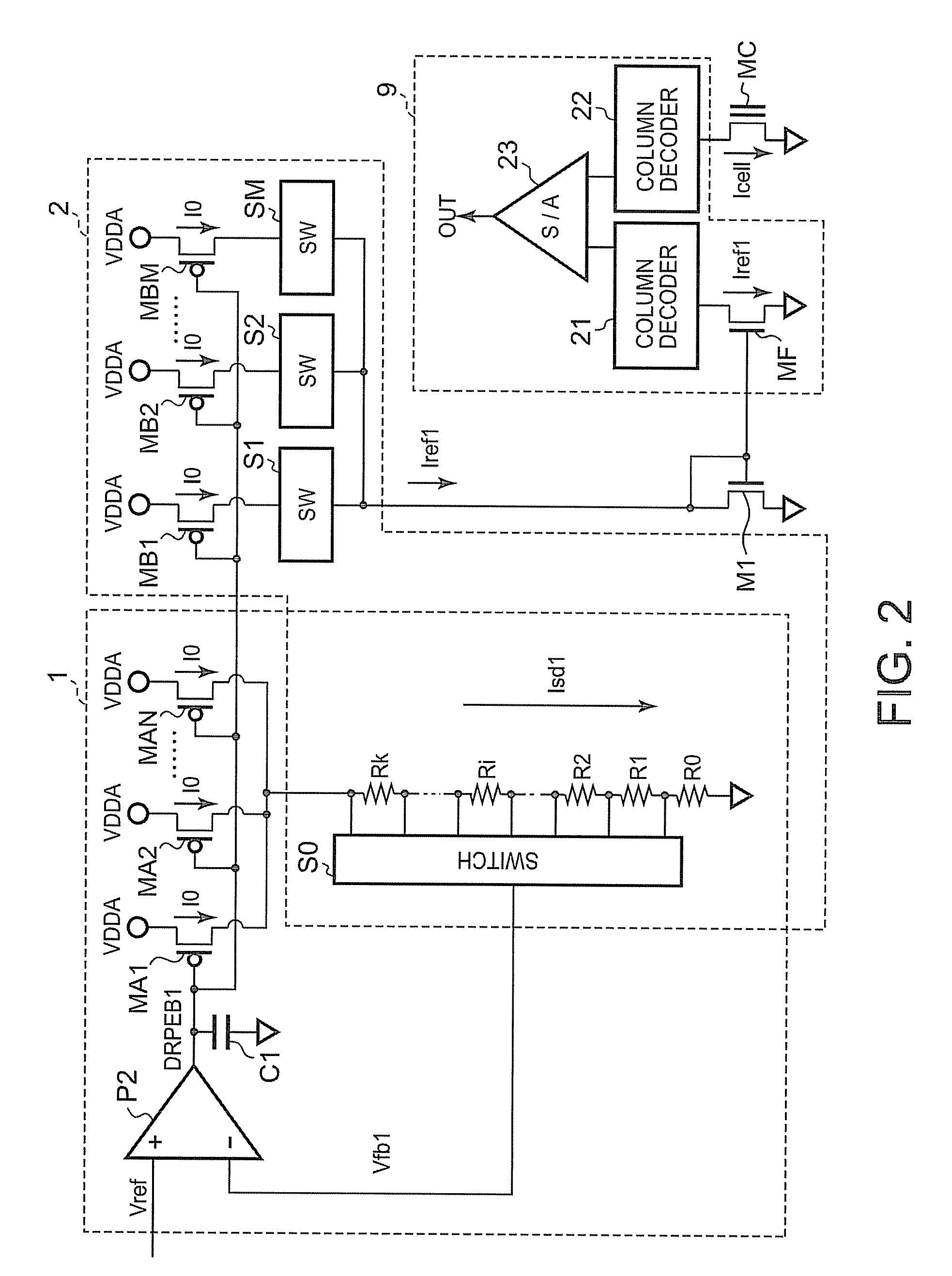
[0079]After the product shipment, when the reference current generating circuit is powered on, a reference current Iref1 trimmed in a first trimming circuit 2 is supplied to a sense circuit 9. In the sense circuit 9, a cell current Icell read from a memory cell MC in FIG. 2 is compared with the reference current Iref1. When the cell current Icell is greater than the reference...


PUM


Abstract

A reference current generating circuit includes first and second standard current generating circuits to generate first and second standard currents, respectively and first and second trimming circuits to generate first and second reference circuits by trimming the standard current values outputted from the standard current generating circuits. The second standard current generating circuit operates for a part of an operation period of the first standard current generating circuit. The value of the first reference current is compared with a value of the second reference current, and controlled so as to approach the value of the second reference current by a trimming controller.

Description

CROSS-REFERENCE TO RELATED APPLICATION[0001]This application is based upon and claims the benefit of priority from prior Japanese Patent Application No. 2009-203111, filed Sep. 2, 2009, the entire contents of which are incorporated herein by reference.BACKGROUND OF THE INVENTION[0002]1. Field of the Invention[0003]The invention relates to a reference current generating circuit, particularly to a reference current generating circuit capable of compensating a deviation of a standard current from a preset value due to aged deterioration of the circuit.[0004]2. Description of the Background Art[0005]With increasing miniaturization of semiconductor devices in recent years, a phenomenon has come to the fore in which a threshold voltage Vth of a field effect transistor is increased with time due to Hot Carrier Injection (HCI) and Negative Bias Temperature Instability (NBTI). As a result of the increased threshold voltage Vth of the field effect transistor, the current of the field effect t...

Claims


Application Information

Patent Timeline
Patent Type & Authority Patents(United States)
IPC IPC(8): G05F3/20
CPCG11C5/147G11C7/14G11C16/28G11C16/30
Inventor FUSE, TSUNEAKIICHIKAWA, MASAKI
Owner KK TOSHIBA
Why Eureka
Try Eureka