
Mobile communication system receiver, path tracking method, and control program thereof

a technology of mobile communication system and control program, which is applied in the direction of transmission, electrical equipment, etc., can solve the problems of deteriorating reception quality, waste of limited resources of finger receivers, and inability to obtain path diversity effect, etc., and achieve the effect of improving path tracking performan

Inactive Publication Date: 2012-04-03
LENOVO INNOVATIONS LTD HONG KONG
View PDF14 Cites 0 Cited by
  • Summary
  • Abstract
  • Description
  • Claims
  • Application Information

AI Technical Summary

Benefits of technology

The present invention provides a path tracking method and a receiver for improving the performance of a spread spectrum communication system in a mobile communication system. The invention addresses the problem of multiple paths and their fluctuations in a mobile communication system, and proposes a method for effectively tracking the paths and extracting signal power peaks from them. The invention also includes a mask region setting function for preventing interference between finger receivers and a priority order setting function for performing path tracking operations on each path. The technical effects of the invention include improved path tracking performance, reduced interference between paths, and improved signal quality.

Problems solved by technology

Thus, even if finger receivers are allocated to such paths and rake combine is performed thereon, the path diversity effect cannot be obtained.
In addition, noise and interference components are superimposed on the demodulated signals, which may possibly result in deteriorating the reception qualities.
Furthermore, limited resources of finger receivers are to be used wastefully.
There are also following issues even if the aforementioned known method is employed.
When such incapability of path tracking operations occurs continuously in fluctuation of the delay profile, in particular, the reception quality becomes deteriorated.
At last, it may result in disconnection of calls.
That is, it is not designed to perform grouping of the paths other than the aforementioned manner.

Method used


Image

  • Mobile communication system receiver, path tracking method, and control program thereof
  • Mobile communication system receiver, path tracking method, and control program thereof
  • Mobile communication system receiver, path tracking method, and control program thereof

Examples


first exemplary embodiment

(First Exemplary Embodiment)

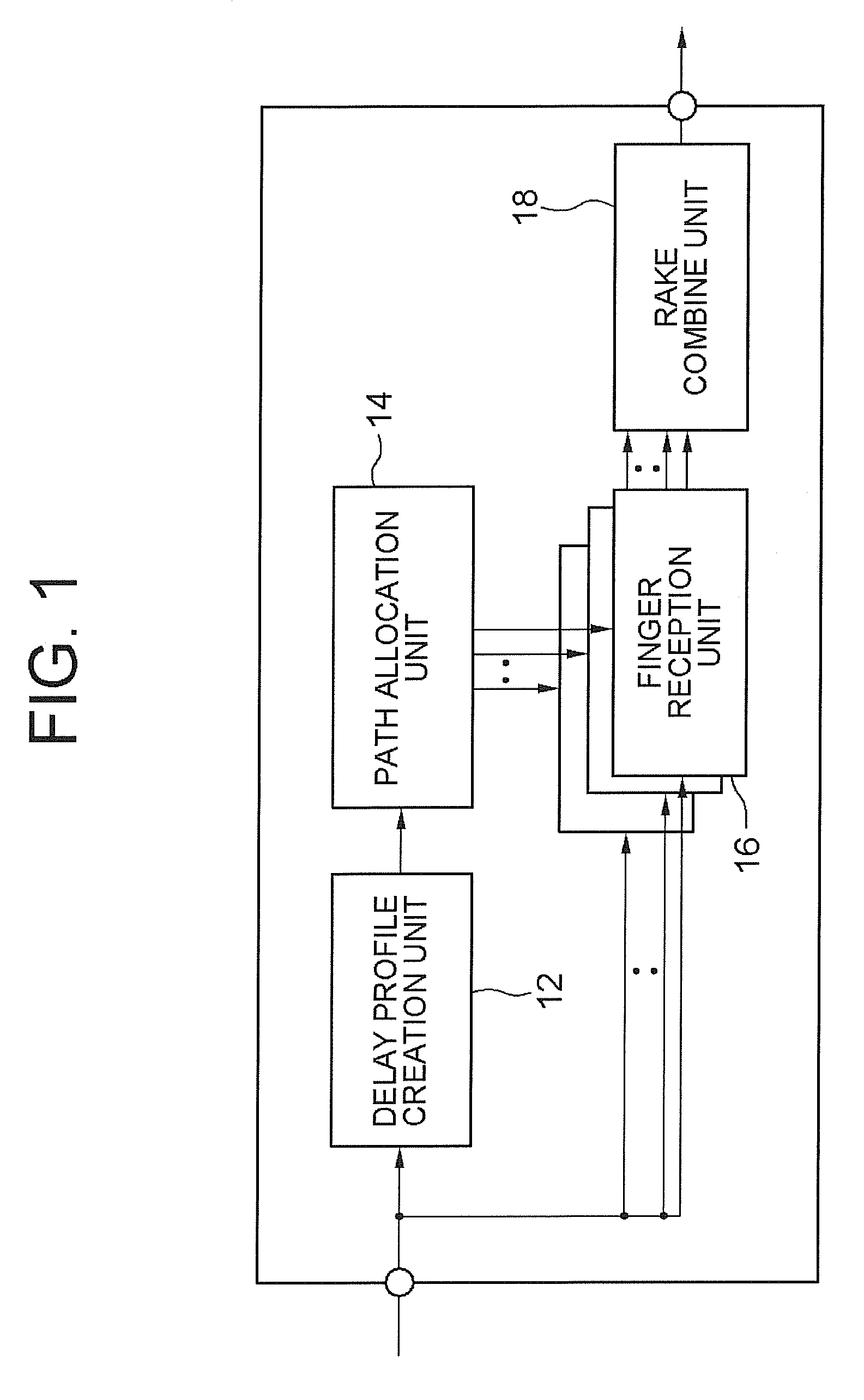
[0033]A case of applying the receiver of the mobile communication system according to the exemplary embodiments to a DS-CDMA mode receiver will be described as a first exemplary embodiment. As described above, a CDMA receiver 1 according to the first exemplary embodiment puts the paths of multipath multiplexed signals received via a plurality of propagation paths into a group when path tracking regions and mask regions set for those paths overlap with each other, gives priority orders to each path within the groups, and performs tracking operations of each path according to the priority orders. As shown in FIG. 1, the CDMA receiver 1 has a delay profile creation unit 12, a path allocation unit 14, a plurality of numbers of finger reception units 16, and a rake combine unit 18. Although not shown, the CDMA receiver has a radio reception unit and an A / D conversion unit. Base band digital signals that are digital signals converted from analog signals in the ...

second exemplary embodiment

(Second Exemplary Embodiment)

[0075]In the first exemplary embodiment, the priority orders when performing the path tracking operations for the paths of the adjacent path group are set based on the signal power values. However, it is not limited only to such case. The priority orders may be set based on the time orders at which the paths of the adjacent path group are separated / extracted. The same effects as those of the first exemplary embodiment can be obtained also with this structure. Further, for grouping the paths, it is possible to put the paths into a group every time the path tracking processing is performed for a single path or at the point where the path tracking processing for all the assumed multipaths is completed.

third exemplary embodiment

(Third Exemplary Embodiment)

[0076]In this exemplary embodiment, the priority orders when performing the path tracking operations for the paths set as the adjacent path group may be set based on the orders of allocating the finger reception units to the paths. The same effects as those of the first exemplary embodiment can be obtained also with this structure.


PUM


Abstract

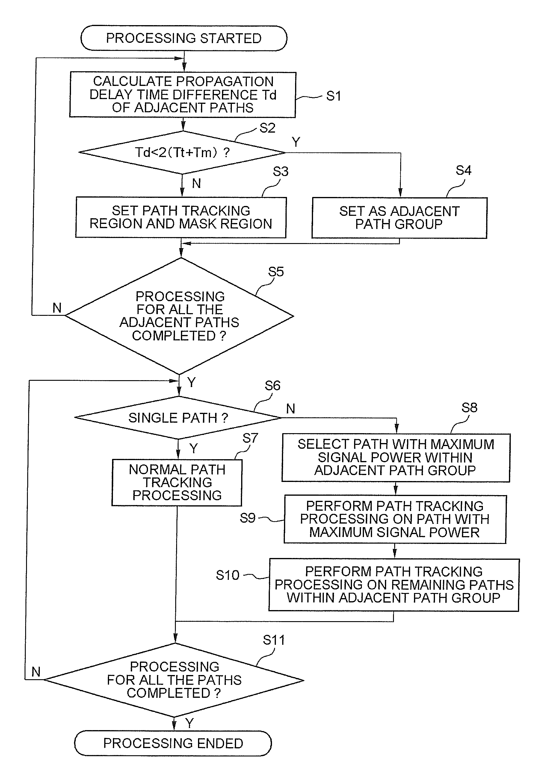
To prevent disabling of the path tracking function.A path allocation unit allocates a signal power peak of a delay profile crated by a delay profile creation unit as a path to a finger reception unit. When tracking a path which has been allocated by the path allocation unit, it is judged whether a path tracking region set for each path is overlapped with a mask region. The path is tracked by performing a process not to cause a loss of a path tracking function due to overlap. Demodulation of the path which has been allocated is performed by a finger reception unit. Each of the demodulated signals outputted from the finger reception unit are rake combined to reproduce the transmitted information signal.

Description

TECHNICAL FIELD[0001]The present invention relates to a mobile communication system receiver, a path tracking method, and a control program thereof. More specifically, the present invention relates to a receiver in a mobile communication system having a fine multipath tracking function, and to a path tracking method as well as a control program thereof.BACKGROUND ART[0002]When trying to transmit an information bit string (data object) to a receiver side in a DS-CDMA mode (Direct Sequence Code Division Multiple Access) used in mobile communication, the information bit string is modulated into spread spectrum signals by spreading the string with spread codes, and the modulated signals in a form of radio signals are transmitted to the receiver side for achieving communication.[0003]Chip rate of the spread codes used in the DS-CDMA mode is a sufficiently high rate for a signal rate of the information bit string, and it is selected as a sufficiently high rate for propagation delay time b...

Claims


Application Information

Patent Timeline
Patent Type & Authority Patents(United States)
IPC IPC(8): H04B1/00H04B1/707
CPCH04B1/7117
Inventor OKUYAMA, TOSHIYUKI
Owner LENOVO INNOVATIONS LTD HONG KONG
Learn More