
Active tuning of temporal dispersion in an ultrashort pulse laser system

a laser system and active tuning technology, applied in the field of active tuning of components in the laser system, can solve the problem of impracticality in fine tuning the dispersion of each laser system in a mass manufacturing environment, and achieve the effect of reducing the temporal width of the output puls

Inactive Publication Date: 2012-04-03
COHERENT INC
View PDF523 Cites 5 Cited by
  • Summary
  • Abstract
  • Description
  • Claims
  • Application Information

AI Technical Summary

Problems solved by technology

It is also impractical to fine tune the dispersion of each laser system in a mass manufacturing environment, since the output of each system must be measured and then its dispersion must be fine tuned.

Method used


Image

  • Active tuning of temporal dispersion in an ultrashort pulse laser system
  • Active tuning of temporal dispersion in an ultrashort pulse laser system
  • Active tuning of temporal dispersion in an ultrashort pulse laser system

Examples


Embodiment Construction

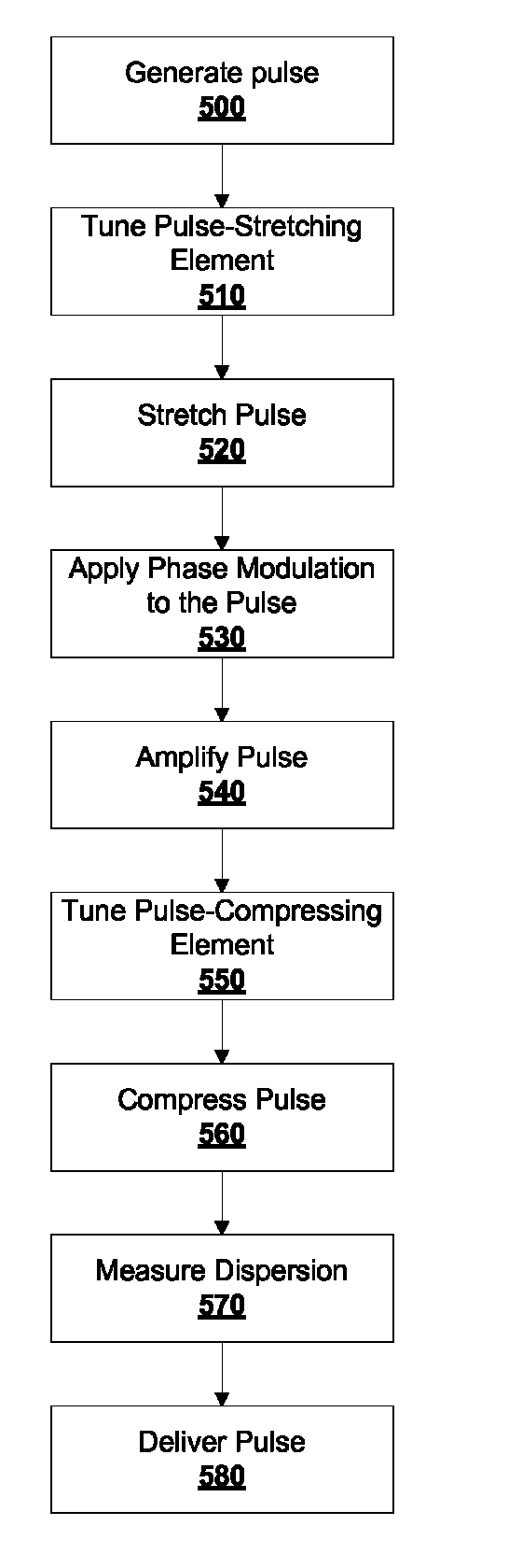
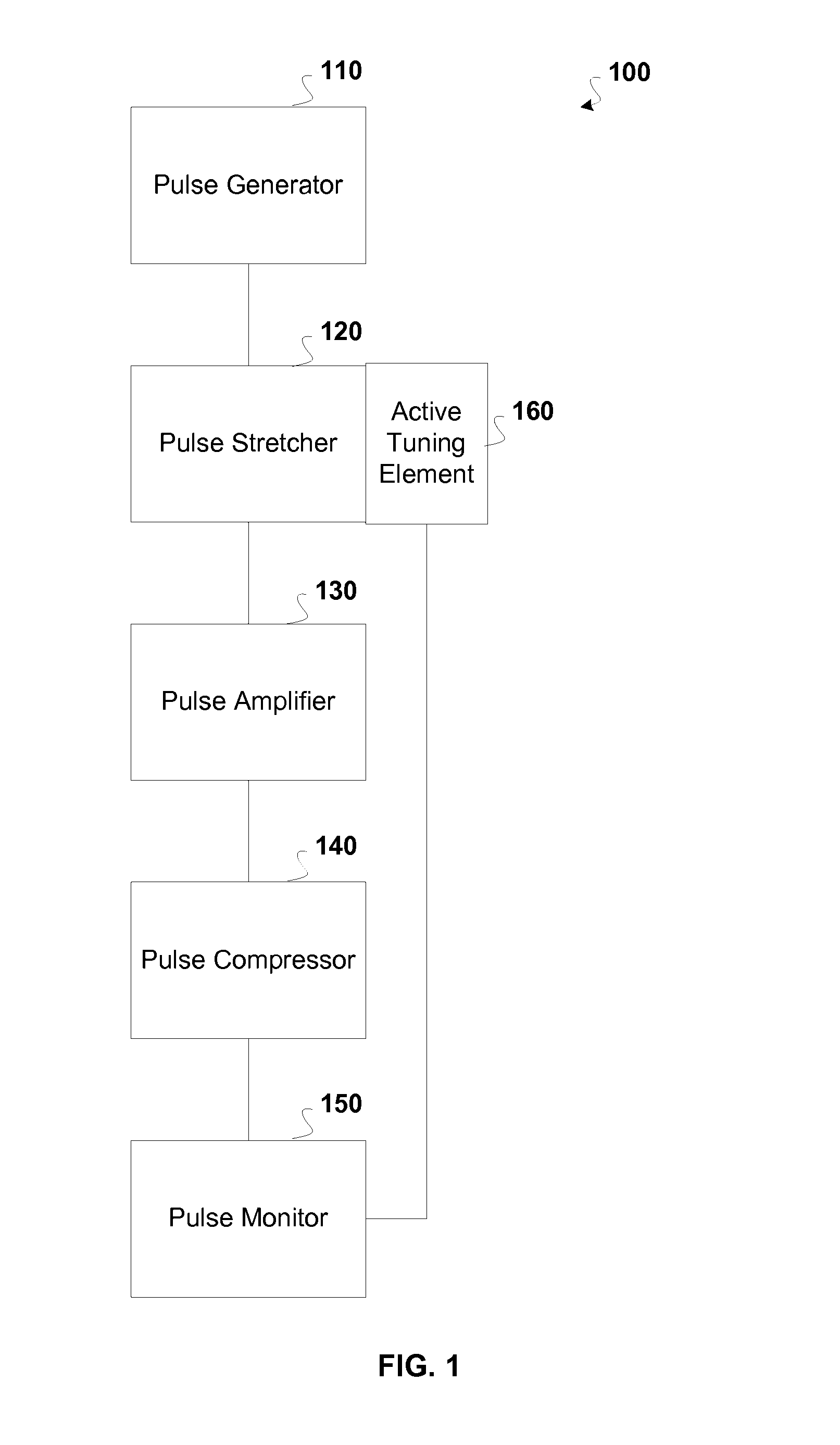
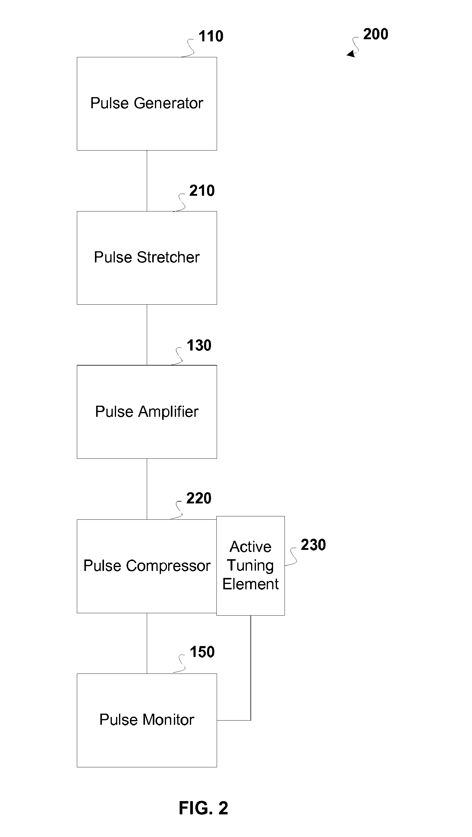
[0019]An active tuning element is incorporated into a chirped pulse amplification system in order to control the overall group velocity dispersion of the system. Control of the overall dispersion enables optimization of a system output pulse. The output pulse is optimized to have specified optical characteristics (e.g. pulse width) at an output of the system and / or at a target surface where the output pulse is delivered.

[0020]Some embodiments include a CPA system comprising Bragg fibers or fiber Bragg gratings configured to change the temporal dispersion of a laser pulse. A fiber Bragg grating comprises a fiber having a number of spaced regions of variable refractive index along its length. In contrast, a Bragg fiber comprises a fiber having a number of concentric layers with varying indices of refraction, see, e.g., U.S. patent application Ser. No. 11 / 112,256, which is hereby incorporated herein by reference. These components can be used to increase or decrease the temporal dispers...


PUM


Abstract

A chirped pulse amplification (CPA) system and method is described wherein the dispersion of the system is tuned by actively tuning one or more system components, for example, using a temperature or strain gradient, or using actinic radiation. In other embodiments, an additional element, such as a modulator, is added to the CPA system to actively to tune the pulse. A pulse monitor is added to the system to measure an output pulse and provide feedback to one or more active tuning elements.

Description

CROSS REFERENCE TO RELATED APPLICATIONS[0001]The present application is a continuation and claims the priority benefit of U.S. patent application Ser. No. 11 / 391,936 filed Mar. 28, 2006 now U.S. Pat. No. 7,822,347, the disclosure of which is incorporated herein by reference.BACKGROUND[0002]1. Field of the Invention[0003]The invention relates to laser systems and more specifically to actively tuning components in a laser system.[0004]2. Related Art[0005]Nearly all high peak power USP laser systems use the technique of chirped pulse amplification (CPA) to produce short-duration high-intensity pulses. Chirped pulse amplification increases the energy of a short pulse while avoiding optical amplifier damage. In this technique, the duration of the pulse is increased by dispersing it temporally as a function of wavelength (a process called “chirping”), amplifying the chirped pulse, and then recompressing the chirped pulse to significantly shorten its duration. By lengthening the pulse in t...

Claims


Application Information

Patent Timeline
Patent Type & Authority Patents(United States)
IPC IPC(8): H04B10/04
CPCH04B10/25137H04B10/508H01S3/0057H01S3/10015H01S3/10023H01S3/1305H01S3/1307H01S3/2308
Inventor BRENNAN, III, JAMES FRANCISVAISSIE, LAURENTMIELKE, MICHAEL MARSHALL
Owner COHERENT INC
Learn More