
Method of grinding a brake disk mounting surface with an annular recess using an inclined grinding wheel

a technology of inclined grinding and mounting surface, which is applied in the direction of gear teeth, brake discs, gear teeth, etc., can solve the problems of increasing the distortion of the brake disk, unstable mounting surface, and likely strange noise when the brake is put, so as to enhance the flatness and straightness of the brake disk mounting surface with respect to an axis of the rolling bearing device for the wheel, and enhance the shape accuracy of the brake disk mounting surface. , the effect of improving the flatness and straightness

Inactive Publication Date: 2012-04-10
JTEKT CORP
View PDF38 Cites 7 Cited by
  • Summary
  • Abstract
  • Description
  • Claims
  • Application Information

AI Technical Summary

Benefits of technology

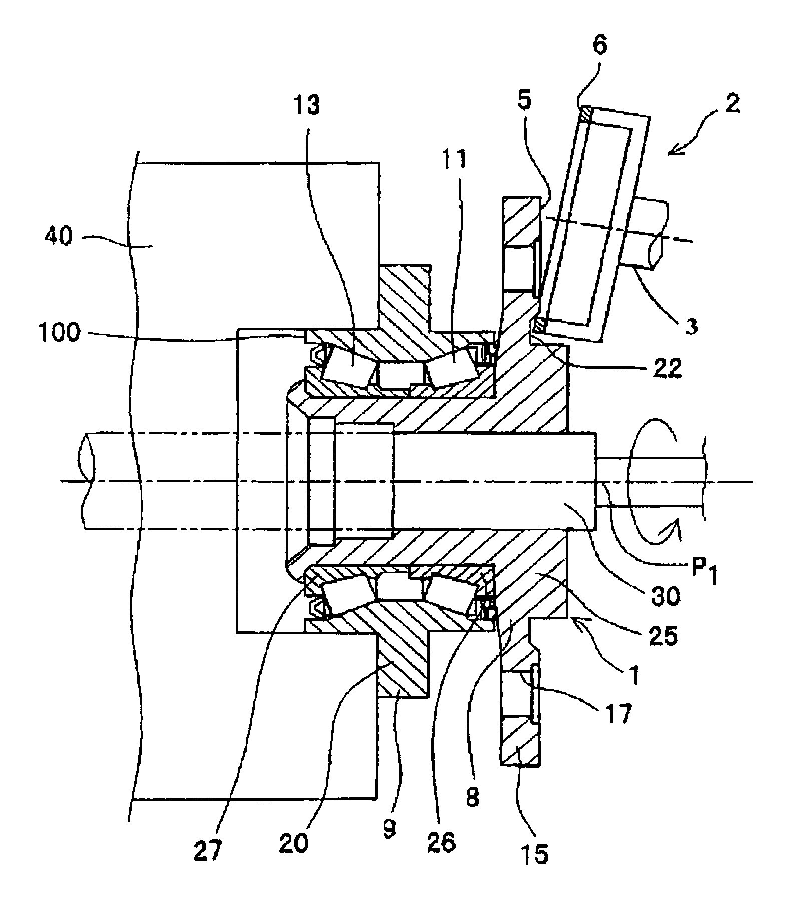
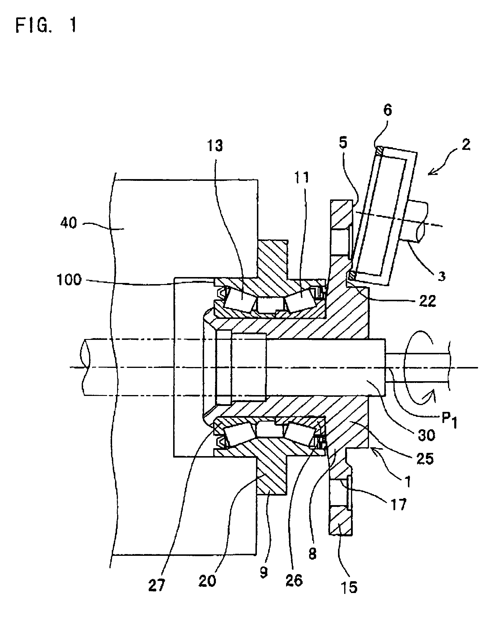
[0011]According to the invention, the brake disk mounting surface is ground by bringing the brake disk mounting surface into contact with the annular grinding wheel, while the outer ring or the inner ring having the brake disk mounting surface is rotated around its center axis, in a state where the grinding surface of the annular grinding wheel is inclined with respect to the brake disk mounting surface so that the distance between the brake disk and the annular grinding wheel grows larger in a direction toward the outer edge of the brake disk mounting surface. Therefore, the brake disk mounting surface can be ground mainly at a part close to its center (a part closer to the recess), and it is possible to make the brake disk mounting surface as a flat surface perpendicular to the rotation center axis. Even though the perpendicular flat surface cannot be obtained, the brake disk mounting surface is formed in a center concave shape, but never formed in a center convex shape, and hence, the brake disk mounting surface can be easily formed in the non center convex shape. As the results, the brake disk can be stably mounted to the brake disk mounting surface, and distortion of the brake disk is reduced. Accordingly, it is possible to fix the brake disk to the brake disk mounting surface reliably and stably, and it is possible to restrain a strange noise from being issued from the brake disk when brake is put on.
[0017]Further, according to the method of producing the rolling bearing device for the wheel of the invention, the brake disk mounting surface is ground in a state where the outer ring and the inner ring and a plurality of the rolling elements are assembled. Therefore, as compared with a method in which the inner and outer ring and the rolling elements are assembled after the brake disk mounting surface has been ground, flatness and straightness of the brake disk mounting surface with respect to the axis of the rolling bearing device for the wheel can be enhanced.

Problems solved by technology

In a rolling bearing device for a wheel, it has been found out that in case where a brake disk mounting surface of the rolling bearing device for the wheel is inclined with respect to a plane which is perpendicular to a rotation center axis of the rolling bearing device for the wheel, mounting of a brake disk to a brake disk mounting surface becomes unstable and distortion of the brake disk is increased, and a strange noise is likely to occur when brake is put on.
Moreover, it is said that a strange noise is most likely to occur, particularly in case where the brake disk mounting surface is in a center convex shape in which the brake disk mounting surface protrudes toward a brake disk side with respect to the plane perpendicular to the rotation center axis of the bearing device in an area close to the center axis.
However, in the above described conventional method of producing the rolling bearing device for the wheel, there is a problem that it is difficult to vary a position of the rotary grinding wheel according to a grinding position of the flange surface, even though the flange surface is intended to be ground in a determined center concave shape, and hence, it is difficult to enhance shaping accuracy of the flange surface with respect to the determined shape, when the flange surface is formed in a center concave shape.Patent Document 1: Japanese Patent Publication No. 2005-1061

Method used


Image

  • Method of grinding a brake disk mounting surface with an annular recess using an inclined grinding wheel
  • Method of grinding a brake disk mounting surface with an annular recess using an inclined grinding wheel
  • Method of grinding a brake disk mounting surface with an annular recess using an inclined grinding wheel

Examples


Embodiment Construction

[0023]Now, the invention will be described in detail, referring to the drawings.

[0024]FIG. 1 is a view showing a rolling bearing device 1 for a wheel and a grinding member 2 during production while a method of producing a rolling bearing device for a wheel in one embodiment of the invention is carried out. More particularly, FIG. 1 is the view showing the rolling bearing device 1 for the wheel and an annular grinding wheel 6 before grinding, while the grinding member 2 is moved close to a brake disk mounting surface 5 of the rolling bearing device 1 for the wheel which has been prepared in a step for preparing the rolling bearing device for the wheel.

[0025]The rolling bearing device 1 for the wheel includes an inner ring 8, an outer ring 9, and taper rollers 11, 13 as an example of rolling elements.

[0026]The inner ring 8 includes an inner shaft 25, a first inner ring 26, and a second inner ring 27. The inner shaft 25 is fitted over an outer periphery of a rotation shaft 30, and has ...


PUM

PropertyMeasurementUnit
widthaaaaaaaaaa
distanceaaaaaaaaaa
angleaaaaaaaaaa

Abstract

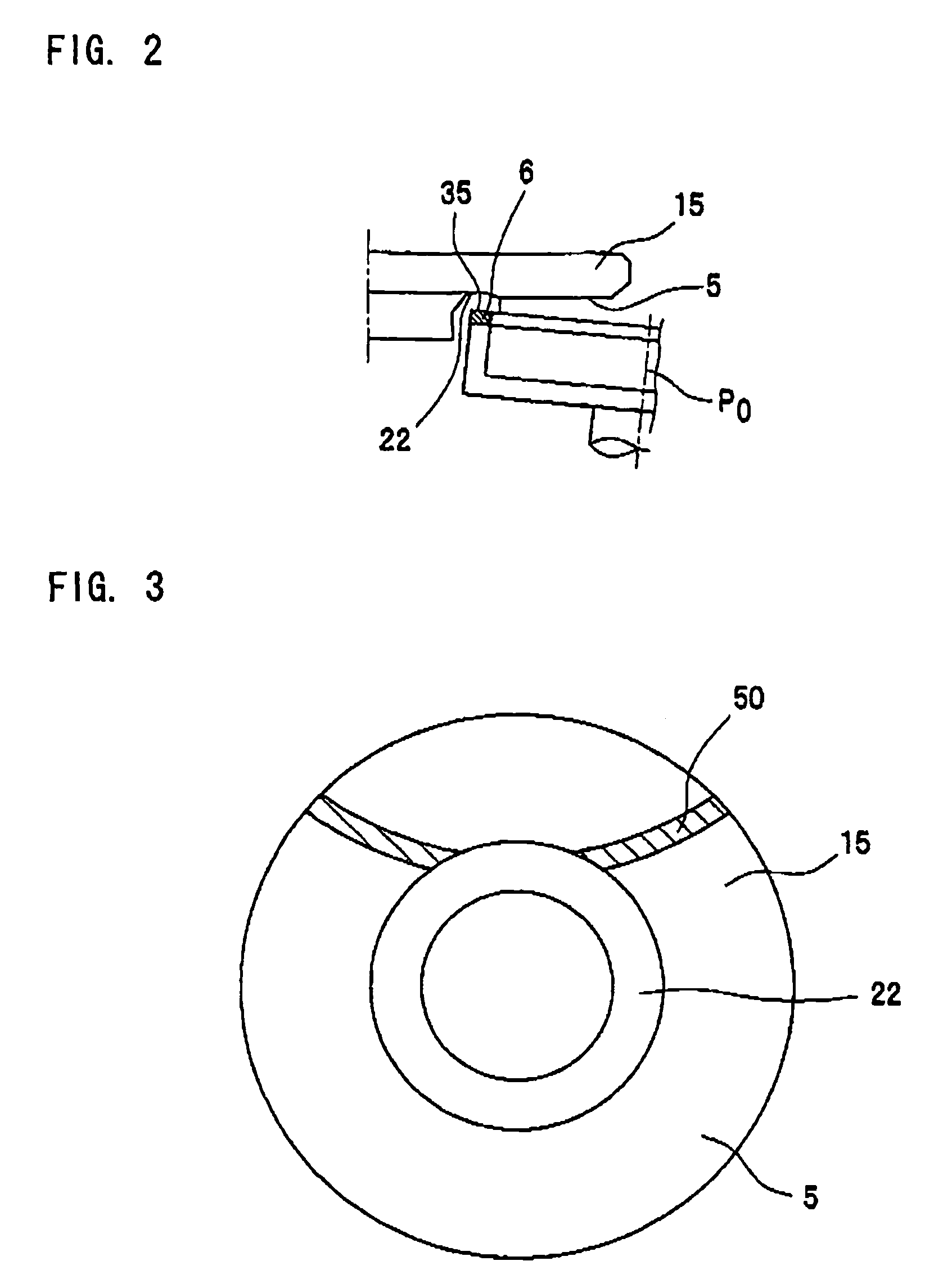
A brake disk mounting surface is ground by bringing it into contact with an annular grinding wheel, while an inner ring having the brake disk mounting surface is rotated around its center axis, in a state where a part of the annular grinding wheel overlaps with a recess over an entire region of the annular grinding wheel in a radial direction, and in a state where a grinding surface of the annular grinding wheel is inclined with respect to the brake disk mounting surface so that a distance between the brake disk mounting surface and the annular grinding wheel grows larger in a direction toward an outer edge of the brake disk mounting surface.

Description

TECHNICAL FIELD[0001]The present invention relates to a method of producing a rolling bearing device for a wheel such as a hub unit, for example.BACKGROUND ART[0002]In a rolling bearing device for a wheel, it has been found out that in case where a brake disk mounting surface of the rolling bearing device for the wheel is inclined with respect to a plane which is perpendicular to a rotation center axis of the rolling bearing device for the wheel, mounting of a brake disk to a brake disk mounting surface becomes unstable and distortion of the brake disk is increased, and a strange noise is likely to occur when brake is put on. Moreover, it is said that a strange noise is most likely to occur, particularly in case where the brake disk mounting surface is in a center convex shape in which the brake disk mounting surface protrudes toward a brake disk side with respect to the plane perpendicular to the rotation center axis of the bearing device in an area close to the center axis. Speaki...

Claims


Application Information

Patent Timeline
Patent Type & Authority Patents(United States)
IPC IPC(8): B24B7/16B24B19/28
CPCB24B7/16B60B27/001F16D65/12Y10T29/49533Y10T29/49536Y10T29/49995Y10T29/49707F16D2065/1384
Inventor FUKAO, TAKESHI
Owner JTEKT CORP
Learn More