Liquid vacuuming and filtering device and method

a vacuuming and filtering device technology, applied in the direction of filtration separation, machines/engines, separation processes, etc., can solve the problems of fluid to be drawn, achieve the effect of facilitating the vacuuming of spilled fluid, facilitating the disposal of fluid and particulate materials, and cleaning up spills

Active Publication Date: 2012-04-10
EXAIR CORP
View PDF112 Cites 25 Cited by
  • Summary
  • Abstract
  • Description
  • Claims
  • Application Information

AI Technical Summary

Benefits of technology

[0011]It is also within the scope of this disclosure to utilize the disclosed device to clean up spills. In such applications, the hose may include a tool, such as a floor attachment, attached to its distil end that would facilitate vacuuming spilled fluid from, for example, a shop floor. The fluid may then be collected within the device and any particulate material filtered from the fluid. Disposal of the fluid and the particulate material thus would be facilitated.

Problems solved by technology

This partial vacuum may cause fluid to be drawn through the flexible hose, through the valve and into the filter within the container interior.

Method used


Image

  • Liquid vacuuming and filtering device and method
  • Liquid vacuuming and filtering device and method
  • Liquid vacuuming and filtering device and method

Examples


Embodiment Construction

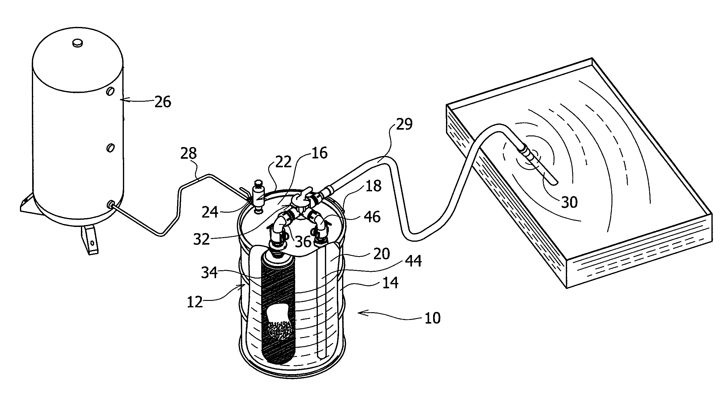
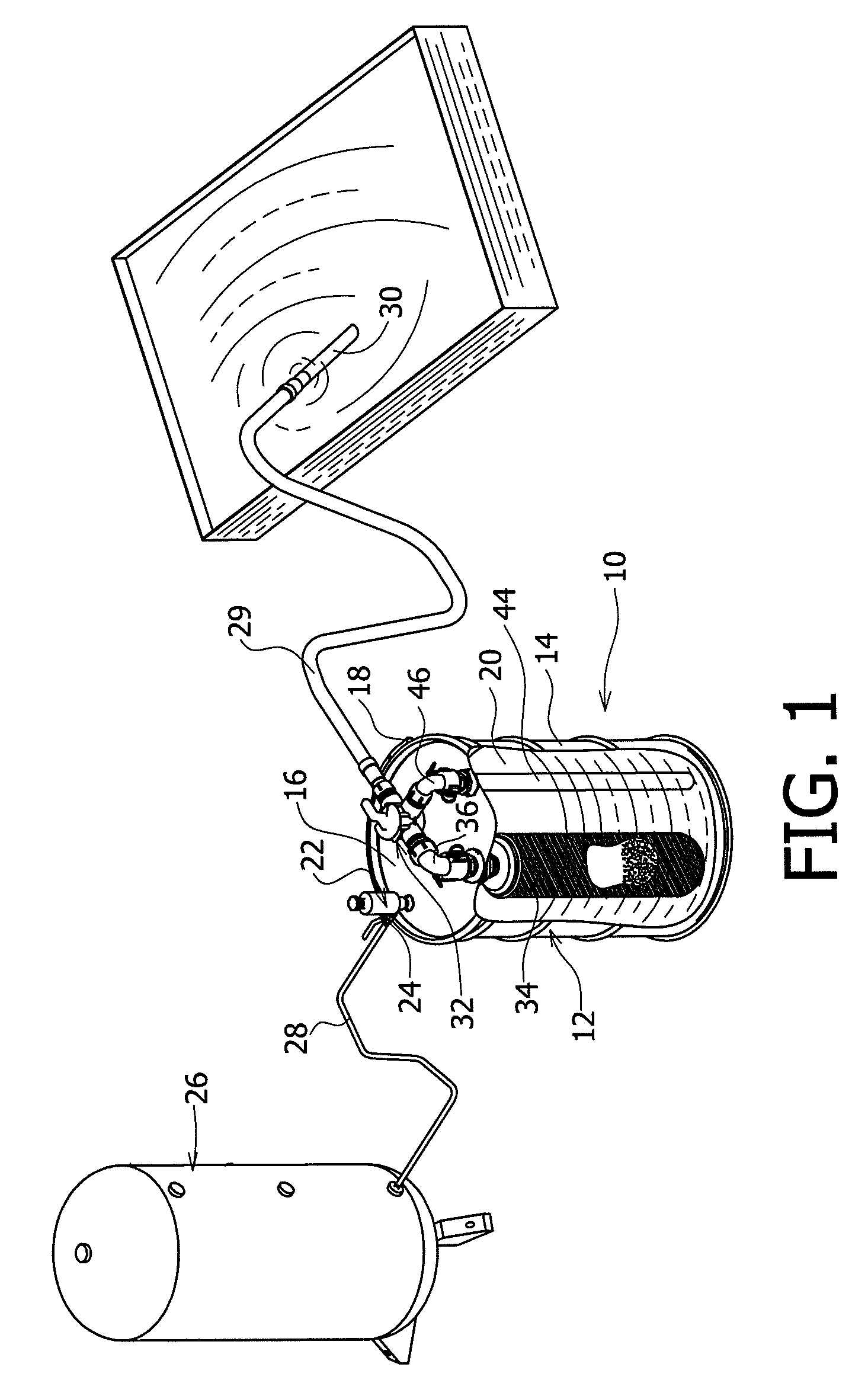
[0018]An embodiment of the disclosed liquid vacuuming and filtering device, generally designated 10, is shown in FIGS. 1 and 2. The device 10 may include a container 12, such as a standard 55-gallon drum. Other containers may be used, such as a 5-gallon or 30-gallon drum or a tank. Plastic containers may be used as well. Any container that is capable of being pressurized positively and negatively without leakage may be used.

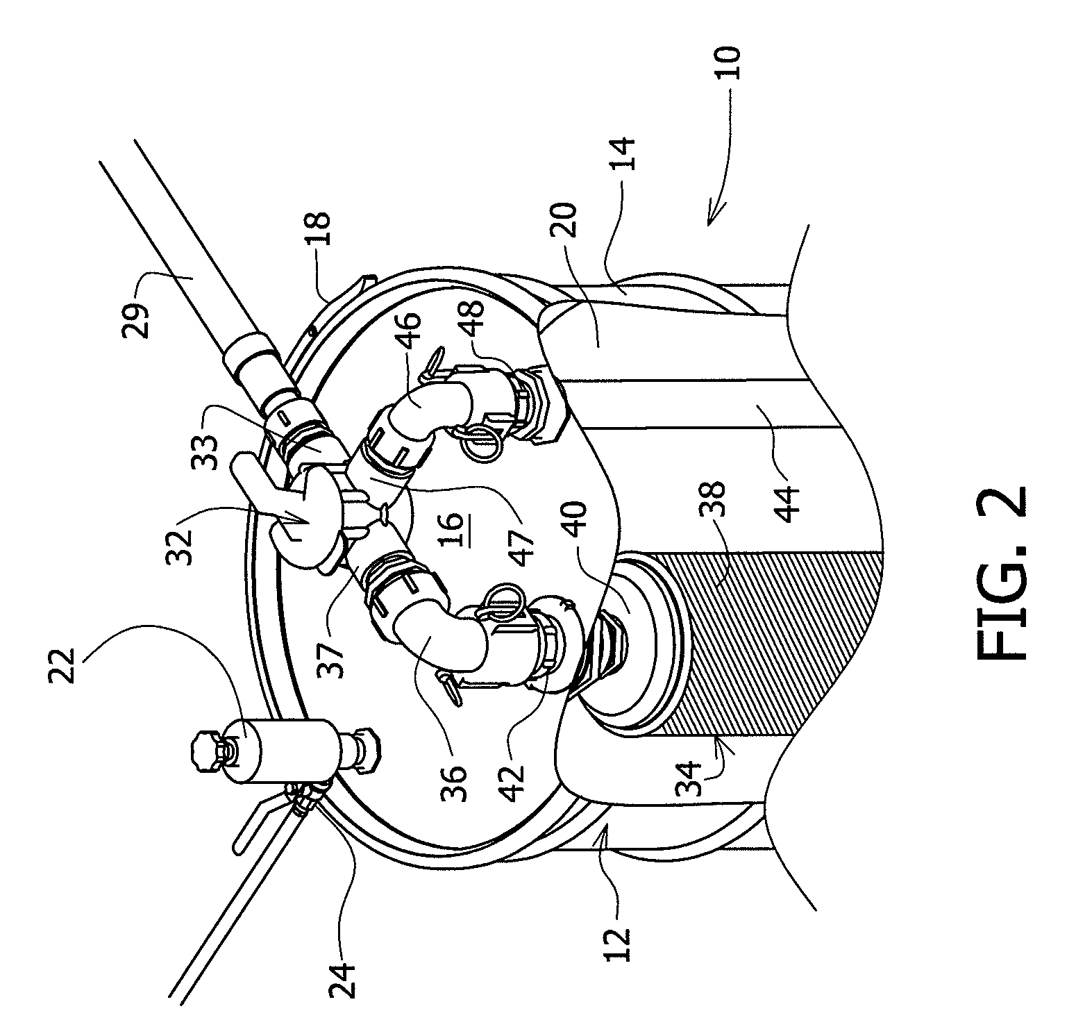
[0019]The container 12 may include a container body 14 and a removable lid 16. The lid 16 may be secured to the body by a drum latch ring 18 to form a sealed interior 20.

[0020]A reversible vacuum pump 22 may be mounted on the lid 16 and may be attached to form a substantially air-tight seal with the lid. The pump 22 may include a shut-off valve 23 (see FIGS. 3 and 4), such as a float valve, that automatically shuts the valve off should the liquid level in the container 12 reach a predetermined maximum level and actuate the valve. This shut-off valve 23 may preven...


PUM

PropertyMeasurementUnit
pore sizesaaaaaaaaaa
pressureaaaaaaaaaa
flexibleaaaaaaaaaa

Abstract

A liquid vacuuming and filtering device may include a container having an interior sealed from the ambient, a vacuum pump in communication with the interior, a two-way valve connected to the container interior, a flexible hose connected to the valve, a filter positioned within the container interior and connected to the valve and a standpipe positioned within the interior and connected to the valve. The vacuum pump may be adjusted to a filling configuration in which the pump evacuates the container interior to a pressure below ambient, which causes fluid to be drawn through the hose, valve and through the filter, which may collect particulates that contaminate the fluid. Filtered fluid then collects within the container. The vacuum pump also may be adjustable to a discharge configuration in which the pump pressurizes the interior to a pressure above ambient, wherein the valve is adjusted to allow filtered fluid within the container to flow through the standpipe, valve and be discharged from the container through the hose. The device may be suitable for reclaiming contaminated fluid used in machining operations, oil or coolant reservoirs, cooking oil and the like.

Description

BACKGROUND[0001]This disclosure is directed to vacuuming devices and, more particularly, to vacuuming devices that collect and filter contaminated fluid and the filtered fluid is subsequently discharged.[0002]Vacuuming devices have been developed in a variety of designs, each to accomplish a specific task or set of tasks. One common configuration of a vacuuming device is a portable vacuum in which a canister, which may be a drum or other enclosed vessel, is used to collect material that is to be vacuumed. A flexible hose that terminates in a rigid wand or other tool is connected to the canister and the wand is placed in or near the material to be collected. Such devices typically include a vacuum pump that lowers the pressure within the sealed canister to below ambient, and the pressure differential causes material to be sucked through the collection hose and collected within the interior of the canister. Such portable devices may be used to vacuum and collect dry particulate materi...

Claims


Application Information

Patent Timeline
Patent Type & Authority Patents(United States)
IPC IPC(8): B01D29/27B01D29/88
CPCB01D29/27B01D2201/204
Inventor PETERS, BRYAN
Owner EXAIR CORP
Why Eureka
Try Eureka