Model train control system

Inactive Publication Date: 2012-04-10
WACHOVIA BANK N A ADMINISTRATIVE AGENT
View PDF72 Cites 94 Cited by
  • Summary
  • Abstract
  • Description
  • Claims
  • Application Information

AI Technical Summary

Benefits of technology

[0019]The present invention provides effects which more realistically model those of a real train. For example, the motor in a model train is proportionally much more powerful compared to its scaled load than the engine of a real train, and thus does not labor noticeably as a real train would. A model train engine quickly accelerates to a new speed even when going uphill with a long train attac

Problems solved by technology

When a real train with a large load is going downhill, it c

Method used


Image

  • Model train control system
  • Model train control system
  • Model train control system

Examples


Embodiment Construction

System

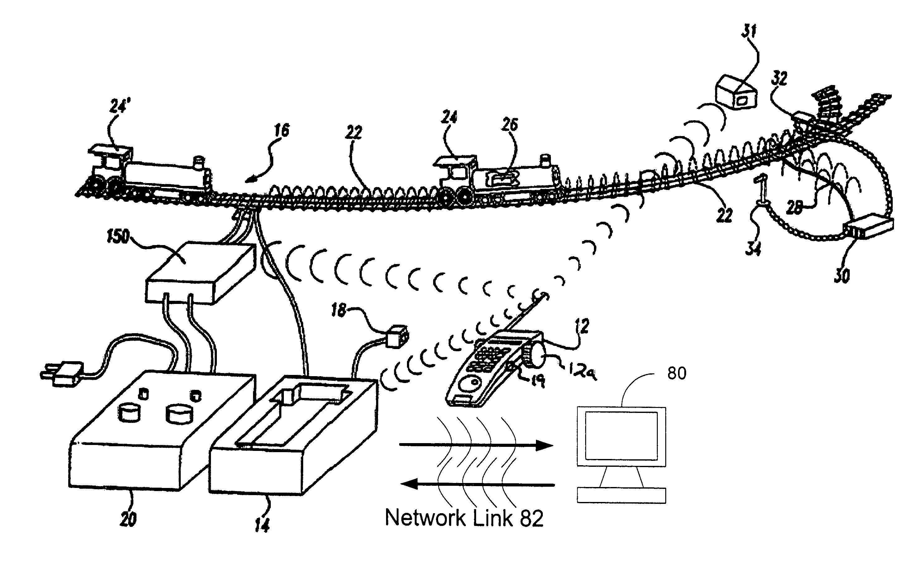
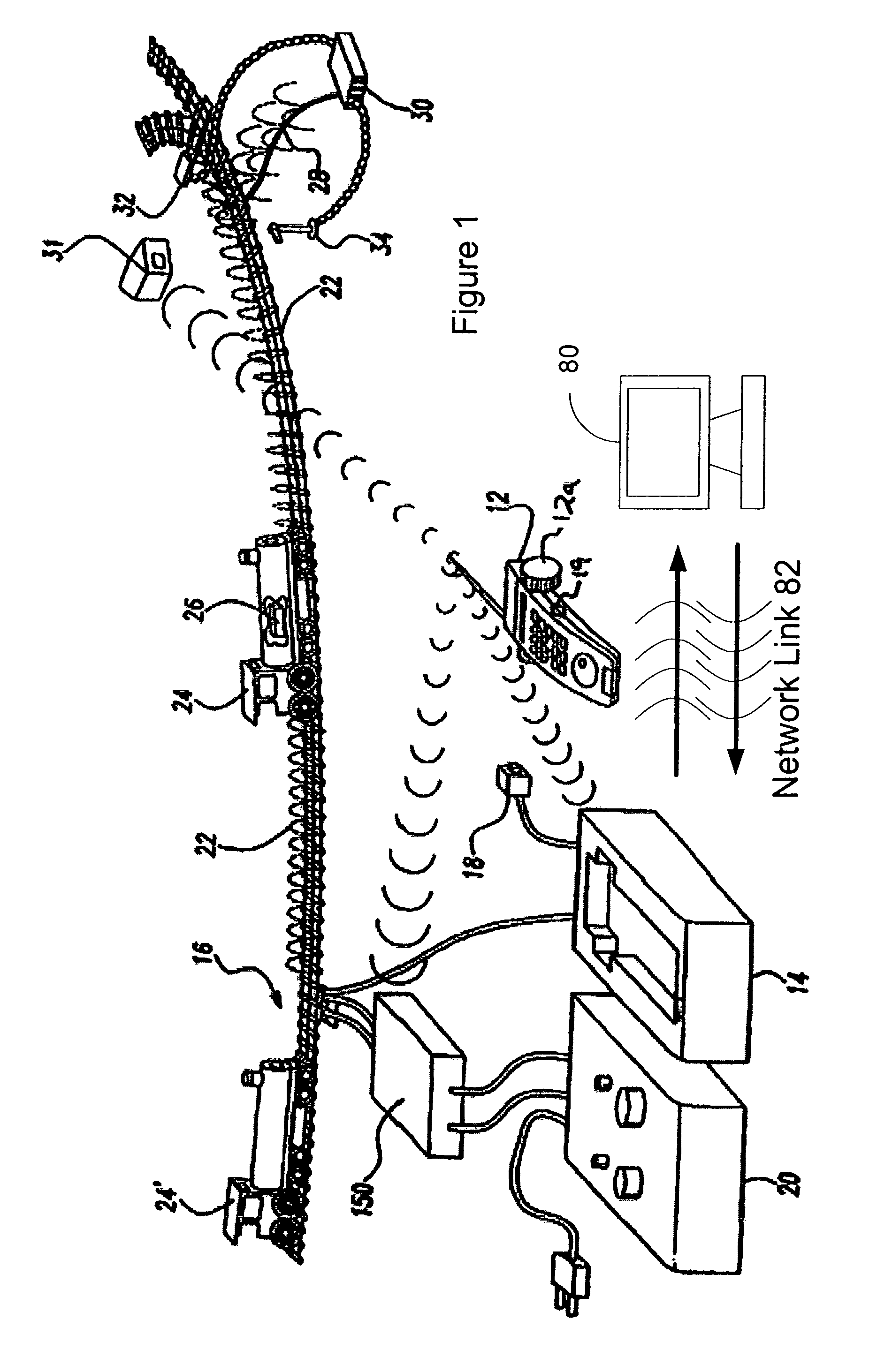
[0041]FIG. 1 is a perspective drawing of an exemplary embodiment of a sample model train layout of a model train track system in accordance with the present invention. A hand-held remote control unit 12 including control input apparatus 12a is used to transmit and receive signals to and from a Central Control Module 14, model locomotive 24, and trackside accessory 31. A power signal is created between the rails of the track by power supply 20 or by Central Control Module 14. Central Control Module 14 can superimpose control signals on the track power signal. Locomotive 24 is configured to receive, decode, and respond to superimposed signals over train track 16.

[0042]Central Control Module 14 is equipped to receive and transmit RF signals, also known as RF control commands. RF control commands can originate from Central Control Module 14, remote control unit 12, trackside accessory 31, or locomotive 24′. RF control commands received by Central Control Module 14 may then be proc...


PUM


Abstract

A model train control system providing a more realistic modeling of the movement, sound, smoke, and lighting effects of a model train is disclosed. A number of dynamic inputs are used to control such effects. Novel features include providing a dynamic variable speed compensator, a dynamic engine load calculator, automatic dynamic momentum, an adjustable train brake, spectrum control, a velocity controller, pressure sensitive effects, a voice activated dispatcher system, a train location and information reporter network, two digit addressing, a traffic control system, accessory control, a model train Central Control Module, and removable memory modules.

Description

CROSS-REFERENCES TO RELATED APPLICATIONS[0001]The instant nonprovisional patent application claims priority as a continuation-in-part to parent U.S. nonprovisional patent application Ser. No. 10 / 723,460, filed Nov. 26, 2003 now U.S. Pat. No. 7,312,590 and incorporated by reference herein for all purposes. Furthermore, the nonprovisional patent application Ser. No. 11 / 188,117, entitled “System for Sending Commands to Train Cars Based on Location in Train,” filed Jul. 22, 2005, the nonprovisional patent application Ser. No. 11 / 187,593, entitled “Force Sensitive Coupler for Trains,” filed Jul. 22, 2005, and the nonprovisional patent application Ser. No. 11 / 187,592, entitled “Model Train Command Protocol Using Front and Back Error Bytes,” filed Jul. 22, 2005 are incorporated by reference herein for all purposes.STATEMENT AS TO RIGHTS TO INVENTIONS MADE UNDER FEDERALLY SPONSORED RESEARCH OR DEVELOPMENT[0002]Not ApplicableREFERENCE TO A “SEQUENCE LISTING,” A TABLE, OR A COMPUTER PROGRAM L...

Claims


Application Information

Patent Timeline
IPC IPC(8): H02P3/00
CPCA63H19/24A63H19/14A63H2019/246
Inventor YOUNG, NEILKOVACH, II, LOUIS G.RICKS, MARK E.RICKS, JOHN T.
Owner WACHOVIA BANK N A ADMINISTRATIVE AGENT
Why Eureka
Try Eureka