Battery charging controller and battery module using the same

a battery module and charging controller technology, applied in the direction of transportation and packaging, arrangements for several simultaneous batteries, ac network voltage adjustment, etc., can solve the problems of battery module usable capacity reduction, lithium battery damage, different battery capacity, etc., to achieve balanced battery charge, low cost, and high cost

Active Publication Date: 2012-04-10
GREEN SOLUTION TECH CO LTD
View PDF19 Cites 14 Cited by
  • Summary
  • Abstract
  • Description
  • Claims
  • Application Information

AI Technical Summary

Benefits of technology

[0006]In view of the high cost of the conventional digital battery balancing controller, the present invention adopts an analog battery charging controller to achieve a balanced charge of batteries. Since the determining circuit of the analog controller comes with an area smaller than that of the analog-to-digital converter, the cost is lower, and the controller can be applied to a battery module composed of any number of batteries to give a broad scope of applicability.

Problems solved by technology

However, the battery capacity is different due to mismatch in manufacture and application.
Since the lithium batteries will be damaged if they are overcharged, therefore the lithium battery charger will stop charging the battery module as soon as any one of the lithium batteries therein is fully charged.
Since each battery self-discharges electric power at a different rate, therefore an unbalanced electric power storage capacity will result among the batteries, and the usable capacity of the battery module is reduced as the using time of the battery increases, and the efficiency of using battery module becomes lower, and the using time of the battery module from fully charged to empty becomes shorter.
However, the voltage of each battery must be converted into a digital signal by an analog-to-digital converter before the digital battery balancing controller 5 processes, and the analog-to-digital converter increases the chip area 10 of the digital battery balancing controller 10 significantly and incurs a high cost.
In addition, the digital battery balancing controller 5 is restricted by its design, such as the ISL9208 chip can support a battery module composed of 5 to 7 pieces of batteries only, and the scope of applicability is limited.

Method used


Image

  • Battery charging controller and battery module using the same
  • Battery charging controller and battery module using the same
  • Battery charging controller and battery module using the same

Examples


Embodiment Construction

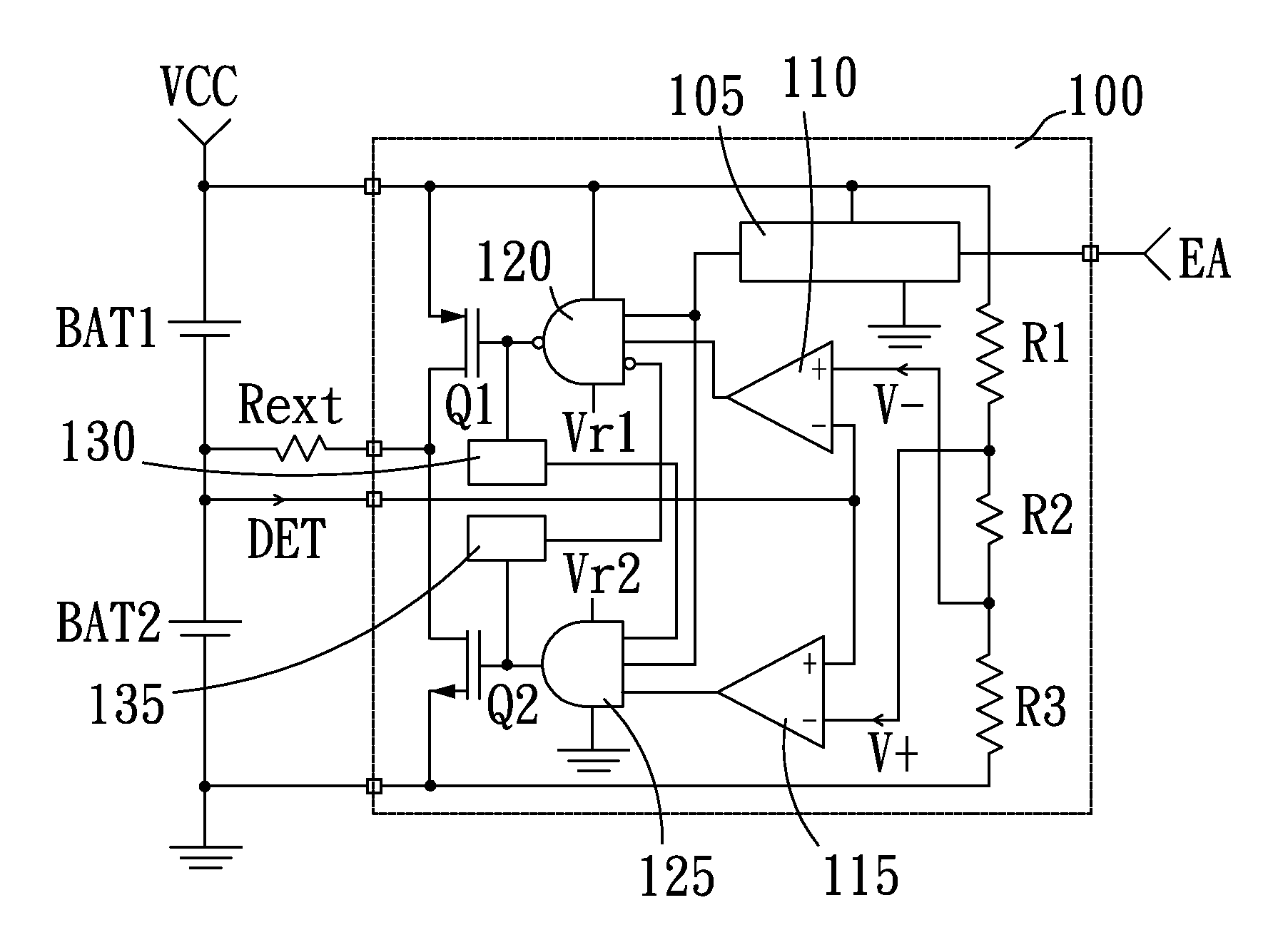
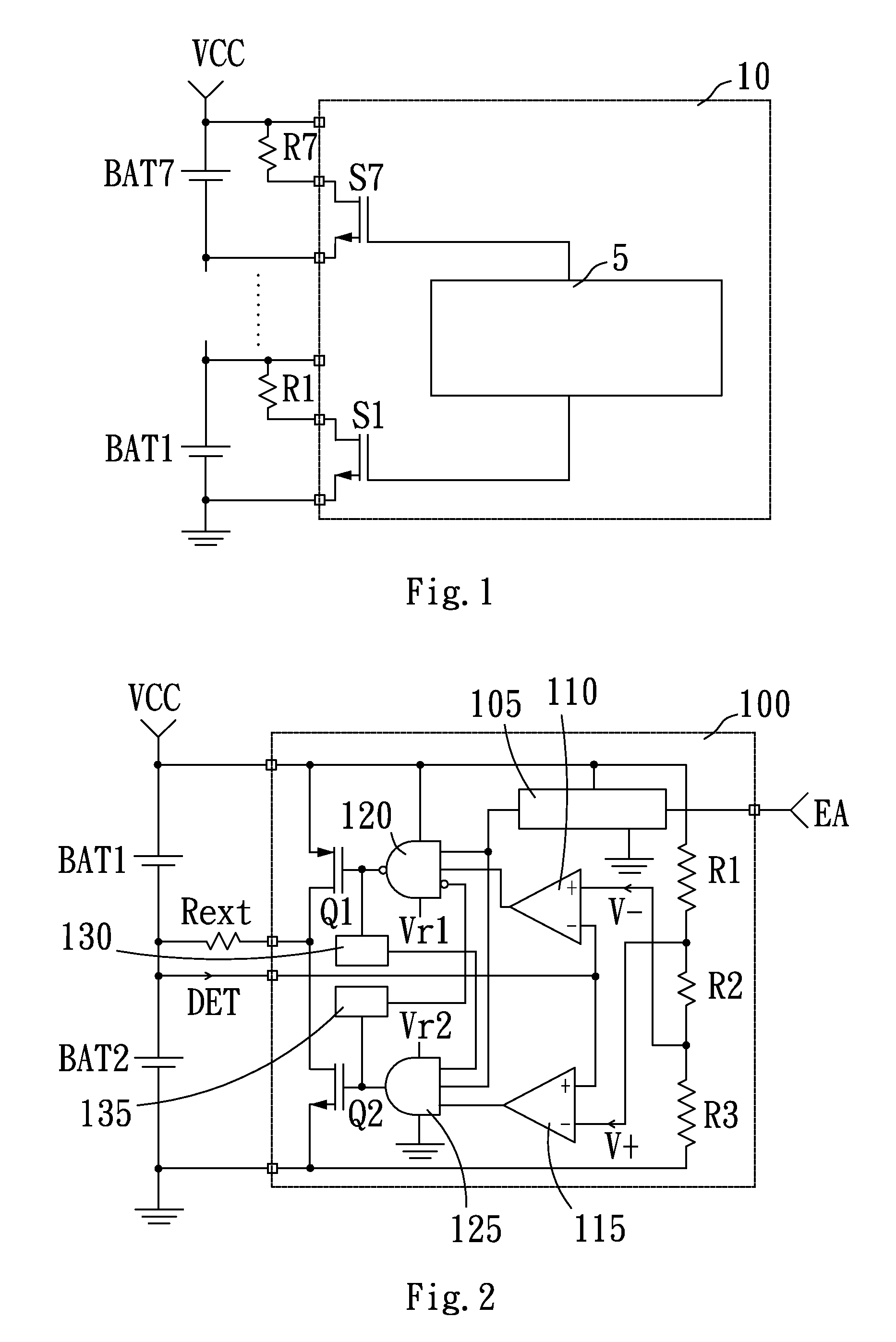
[0013]With reference to FIG. 2 for a schematic circuit diagram of a battery balanced charging controller in accordance with a preferred embodiment of the present invention, the battery balanced charging controller 100 comprises a voltage divider, a switch module and a balance circuit. The voltage divider comprises a first resistor R1, a second resistor R2 and a third resistor R3, and the first resistor R1 is coupled to a positive terminal of a first battery BAT1, and the third resistor R3 is coupled to a negative terminal of a second battery BAT2. The second resistor R2 is coupled to the first resistor R1 for producing an upper reference potential level V+, and coupled to the third resistor R3 for producing a lower reference potential level V−. The impedances of the first resistor R1 and the third resistor R3 are equal, and the impedance of the second resistor R2 is smaller than the impedance of the first resistor, preferably R1:R2:R3=100:1:100. The switch module comprises a first s...


PUM


Abstract

The present invention discloses a battery charging controller for achieving a balanced battery charge. The battery charging controller includes a voltage divider, a switch module and a balance circuit. A reference voltage generated by the voltage divide is used to determine which battery unit in a battery module has an insufficient voltage lower than the others, so that the balance circuit controls the switch module to allow a larger current to charge a lower-voltage battery than a higher-voltage battery, so as to result in substantially the same voltage for each fully charged battery of the battery module.

Description

FIELD OF THE INVENTION[0001]The present invention relates to a battery charging controller and a battery module using the battery charging controller, and more particularly to a battery charging controller for balancing a battery charge and a battery module using the battery charging controller.BACKGROUND OF THE INVENTION[0002]As portable electronic products are developed rapidly, the demand for rechargeable batteries becomes increasingly larger. Rechargeable batteries include the conventional Ni—Ca battery, Ni—H battery, and Li-ion battery as well as the recently developed Li-polymer battery. The voltage provided by different type of rechargeable battery varies, and the required operating voltages of the portable electronic products are different. Therefore, battery manufacturers usually connect several batteries in series to produce a battery module for providing a voltage capable of meeting the operating voltage requirement of the portable electronic products.[0003]When the elect...

Claims


Application Information

Patent Timeline
Patent Type & Authority Patents(United States)
IPC IPC(8): H02J7/00H02J3/14H02J7/02
CPCH02J7/0016
Inventor YU, CHUNG-CHESHIU, SHIAN-SUNG
Owner GREEN SOLUTION TECH CO LTD
Why Eureka
Try Eureka