
Multi-stage differential warping amplifier and method

a technology of differential warping amplifier and amplifier, applied in the field of signal processing, can solve the problems of imposing frequency-dependent degradation on signals carried over the medium, lossy signal transmission medium of most communication systems, and limited data rate and bandwidth

Active Publication Date: 2012-04-17
ACTELIS NETWORKS INC
View PDF18 Cites 3 Cited by
  • Summary
  • Abstract
  • Description
  • Claims
  • Application Information

AI Technical Summary

Benefits of technology

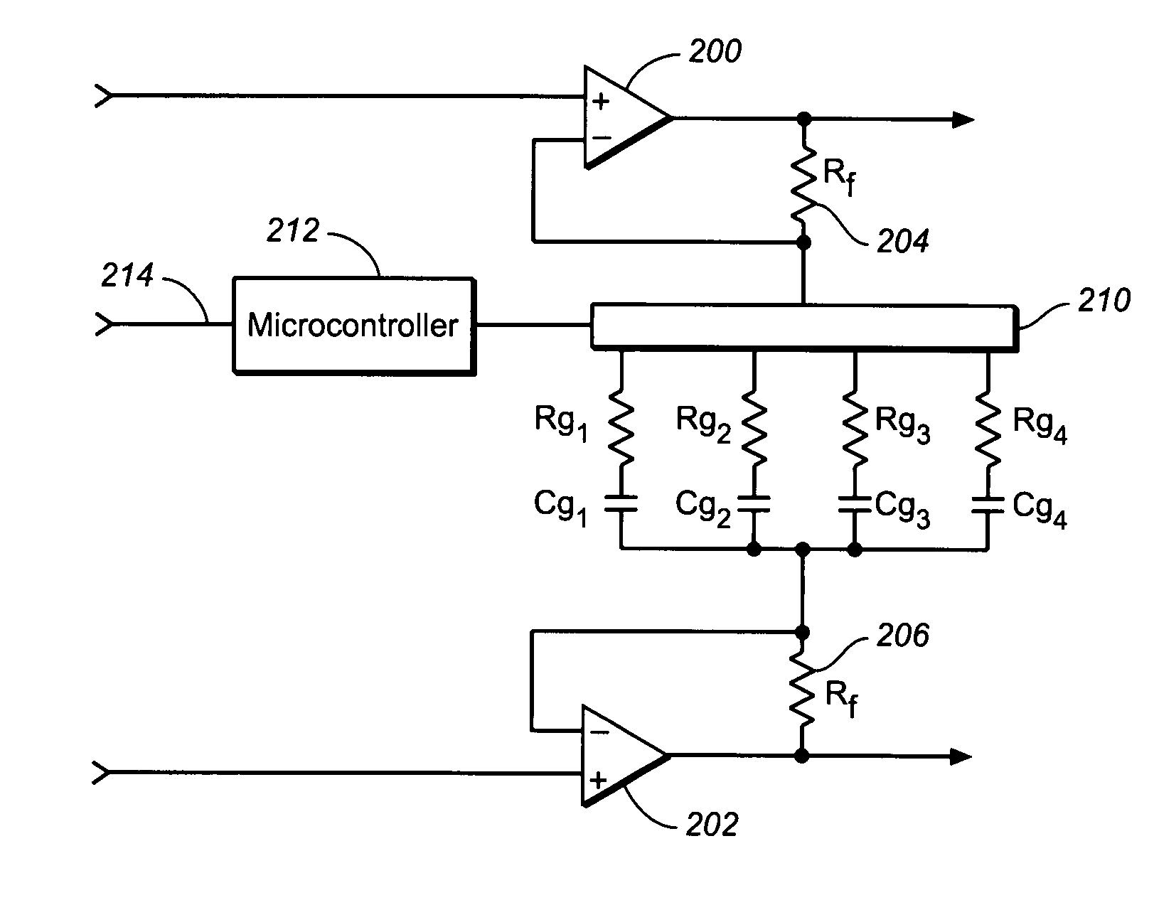
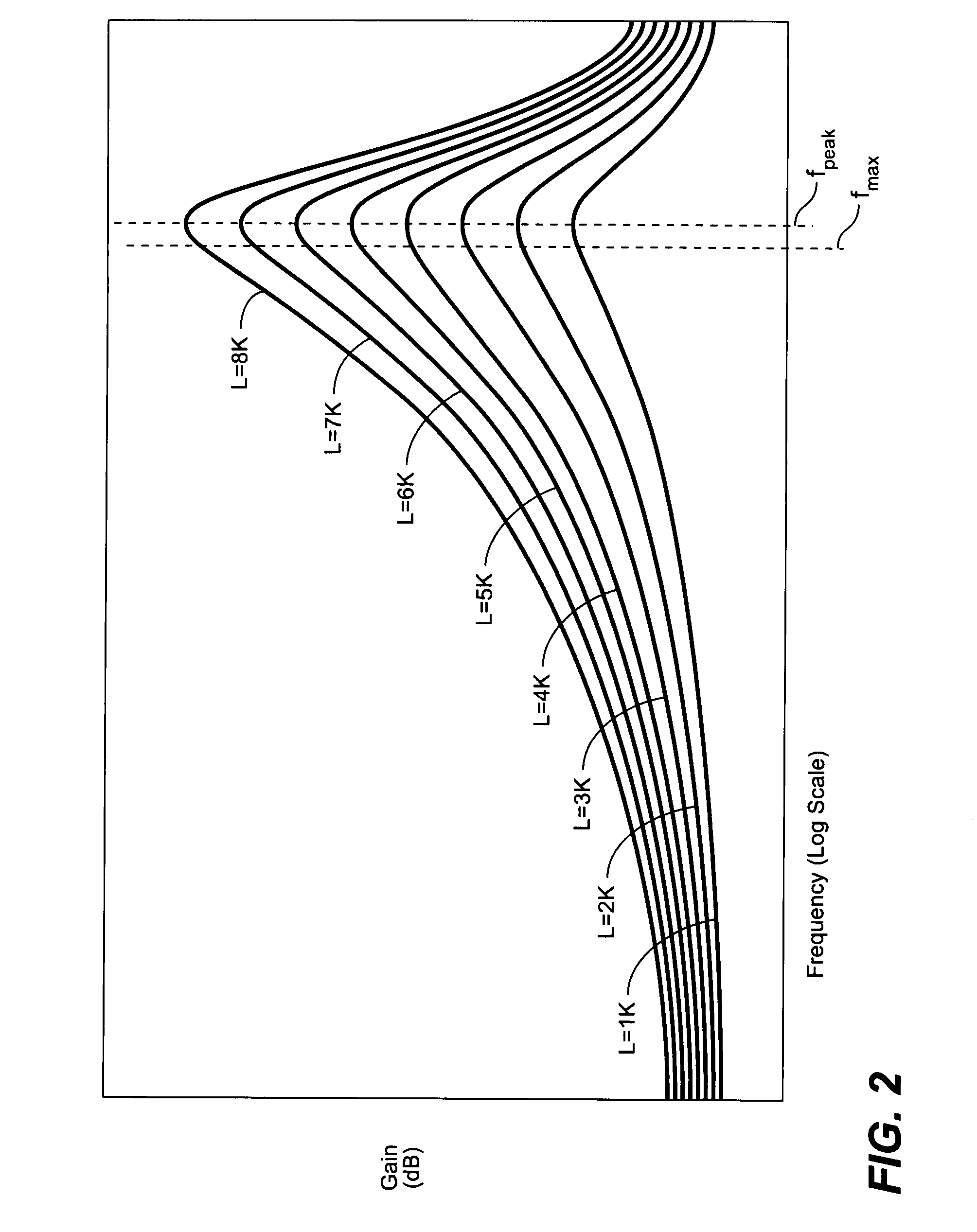
"The invention provides electronic circuits and methods for compensating for frequency-dependent signal impairment in transmission lines. This allows for high-speed and high-bit rate analog and digital transmission via lossy transmission lines. The invention offers warping amplifiers and methods that are low power and low noise, and can be used in different locations in the transmission line. The warping amplifier compensates for the attenuation of the transmission line by amplifying signals with a gain-frequency response characteristic that matches the inverse of the attenuation-frequency characteristic of the transmission line. The method involves calculating resistive and capacitive values to determine the gain-frequency characteristic of the differential amplifier, simulating the frequency response, adjusting the resistive and capacitive values to match the target peak frequency, and adjusting the resistive and capacitive values to match the target gain. The invention also includes compensating for the remaining attenuation by further warping the signals."

Problems solved by technology

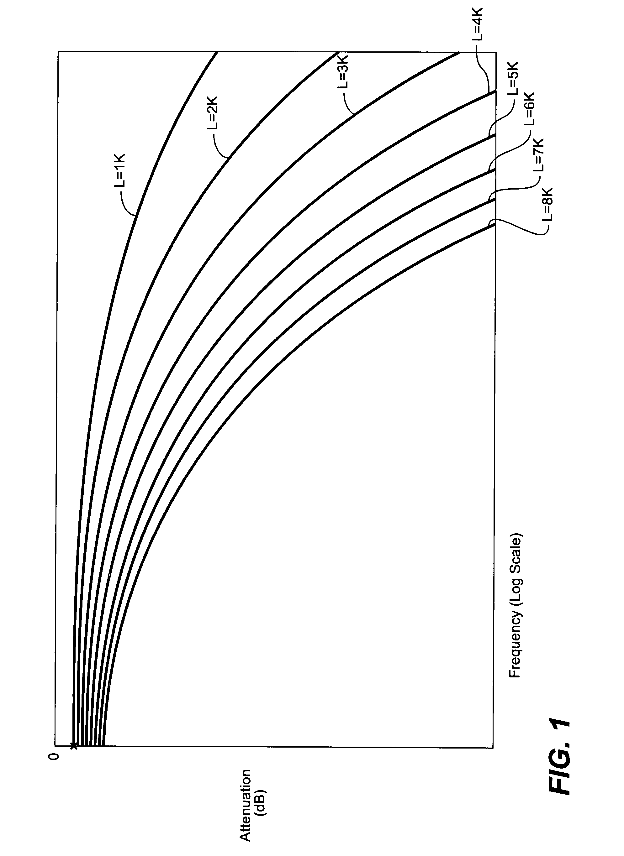
The signal transmission medium of most communication systems is lossy regardless of whether the transmission medium is a transmission line, an optical fiber, or free space, and will characteristically impose a frequency-dependent degradation on signals carried over the medium.
The achievable data rate and bandwidth are also limited by other factors such as group delay, which is a function of frequency, as well as crosstalk and noise.
All types of transmission media exhibit signal degradation, and some types are more lossy than others.
The lossy characteristics of such transmission lines, however, limit their utility as a transmission medium for this type of high-speed, high-bit rate data signals.

Method used


Image

  • Multi-stage differential warping amplifier and method
  • Multi-stage differential warping amplifier and method
  • Multi-stage differential warping amplifier and method

Examples


Embodiment Construction

[0022]The invention is particularly well adapted for use in compensating for frequency-dependent impairment of high bit rate digital signals on transmission lines such as a twisted pair, for example, and will be described in that context. It will be appreciated, however, that this is illustrative of only one utility of the invention, and that the invention is applicable to other types of transmission lines, including shielded or unshielded conductors, coaxial cable, etc., as well as to the equalization and compensation of frequency-dependent impairments to electrical signals more generally, as well as to other types of communications systems and transmission media.

[0023]For many types of transmission lines, attenuation is the most significant impairment imposed by the transmission lines on signal transmission. For shielded or unshielded twisted pair, for example, crosstalk and common mode noise may also be pronounced signal impairment factors. Because signal attenuation increases ra...


PUM


Abstract

A multi-stage differential amplifier and method provides a gain versus frequency warping response characteristic that equalizes a transmission line of a given length to compensate for frequency-dependent attenuation. The warping response characteristic comprises the inverse of the attenuation versus frequency characteristic of the line, and affords a substantially flat system gain response over a predetermined frequency spectrum. The individual amplifier stages employ operational amplifiers, and are designed using SPICE simulations such that the individual responses of the stages are tailored so they combine to provide the required overall warping response to compensate the line.

Description

CROSS-REFERENCE TO RELATED APPLICATIONS[0001]This application is a continuation-in-part of application Ser. No. 11 / 316,781, filed Dec. 23, 2005 now U.S. Pat. No. 7,587,042, which is a continuation-in-part of application Ser. No. 10 / 889,090, filed Jul. 12, 2004 now U.S. Pat. No. 7,110,528, the disclosures of which are incorporated by reference herein.BACKGROUND OF THE INVENTION[0002]This invention relates generally to signal processing in communications systems to equalize the signal transmission medium and to compensate for frequency-dependent signal impairment, and more particularly to electronics circuits and methods for equalizing and compensating for frequency-dependent signal attenuation and the like.[0003]The signal transmission medium of most communication systems is lossy regardless of whether the transmission medium is a transmission line, an optical fiber, or free space, and will characteristically impose a frequency-dependent degradation on signals carried over the medium...

Claims


Application Information

Patent Timeline
Patent Type & Authority Patents(United States)
IPC IPC(8): H04M9/00H04M7/04
CPCH04B3/08H04B3/143H04B3/36H04M11/062H04M1/738H04M3/304H04M3/40H04L25/03878
Inventor LARZABAL, LUIS R. A.PONGANIS, EDWARD P.FRASER, DAVID F.
Owner ACTELIS NETWORKS INC
Learn More