Method and device for detecting oscillatory failures in a position servocontrol subsystem of an aircraft control surface

a technology of position servo control and aircraft control surface, which is applied in the direction of vehicle registration/indication, vehicle navigation, amplifier modification to reduce noise influence, etc., can solve the problems of slaved airfoil oscillation, damage to the structure of the aircraft, and mechanical part of the actuator malfunction or breakage, so as to enhance the performance of monitoring oscillatory faults and improve the quality of said models. , the effect of enhancing the performance of the method

Active Publication Date: 2012-04-17
CENT NAT DE LA RECHERCHE SCI +2
View PDF12 Cites 17 Cited by
  • Summary
  • Abstract
  • Description
  • Claims
  • Application Information

AI Technical Summary

Benefits of technology

[0044]Thus, by virtue of the invention, real-time estimation of the values of parameters of the model is carried out (the values thus estimated being reinjected into the model), thereby making it possible to improve the qualities of said model and thus to enhance the performance of the method for detecting oscillatory faults. The performance of the monitoring of the oscillatory faults is consequently enhanced both in terms of detection and robustness. This contributes especially to overall optimization of an aircraft, in particular at the level of the structural layout of the latter.
[0045]Furthermore, as specified below, the method in accordance with the invention avoids resorting to sensors or to specific gauges for estimating the parameter(s) of the model of the actuator and therefore has no negative impact on the mass budget.
[0061]said parameter θ3 represents a damping coefficient which makes it possible to estimate a particular loading generated by the actuator (damping of the adjacent actuator in the case of two actuators per airfoil).

Problems solved by technology

It is known that such a slaving chain comprises electronic components which are liable, in failed mode, to generate a spurious signal which may cause the slaved airfoil to oscillate.
Another possible cause of the oscillation is the malfunction or breakage of a mechanical part of the actuator.
It is known moreover that, when an oscillatory fault such as this exhibits a frequency which lies inside the bandwidth of the actuator, its effect is:to generate significant loads on the structure of the aircraft, thereby making it necessary to reinforce this structure, if a dedicated device does not enable this fault to be detected;to generate excessive loads in the event of excitation of one of the natural modes of vibration of the aircraft (phenomenon of resonance, aeroelastic coupling), and this may, in the extreme case, result in damage to the structure of the aircraft;to accelerate the fatigue of the actuator or actuators used; andto reduce the comfort of the aircraft's passengers.
Complete coverage of oscillatory faults such as these would require overly expensive structural reinforcements of the aircraft.
Consequently, to a particular family of aircraft there always corresponds a particular standard solution, which does not exhibit any guarantee of being applicable to another, existing or future, family of aircraft.
Moreover, the standard monitoring solutions generally exhibit restricted coverage, usually only undertaking detection of the oscillations generated by a particular component of the slaving chain.
So, the fact of fixing these parameters at constant values degrades the quality of said model.
The use of constant parameters therefore limits the performance of the detection method disclosed by patent application FR-05 12000.
So, for an existing airplane, if one were induced to decrease the fault level to be detected, this standard method could no longer be adapted to such a decrease.
This could result in greater demands on the structural layout of the airplane (saving of mass) and therefore in more constraining detection levels and confirmation times. In such a situation, the aforesaid detection method would no longer be sufficiently efficacious.

Method used


Image

  • Method and device for detecting oscillatory failures in a position servocontrol subsystem of an aircraft control surface
  • Method and device for detecting oscillatory failures in a position servocontrol subsystem of an aircraft control surface
  • Method and device for detecting oscillatory failures in a position servocontrol subsystem of an aircraft control surface

Examples


Embodiment Construction

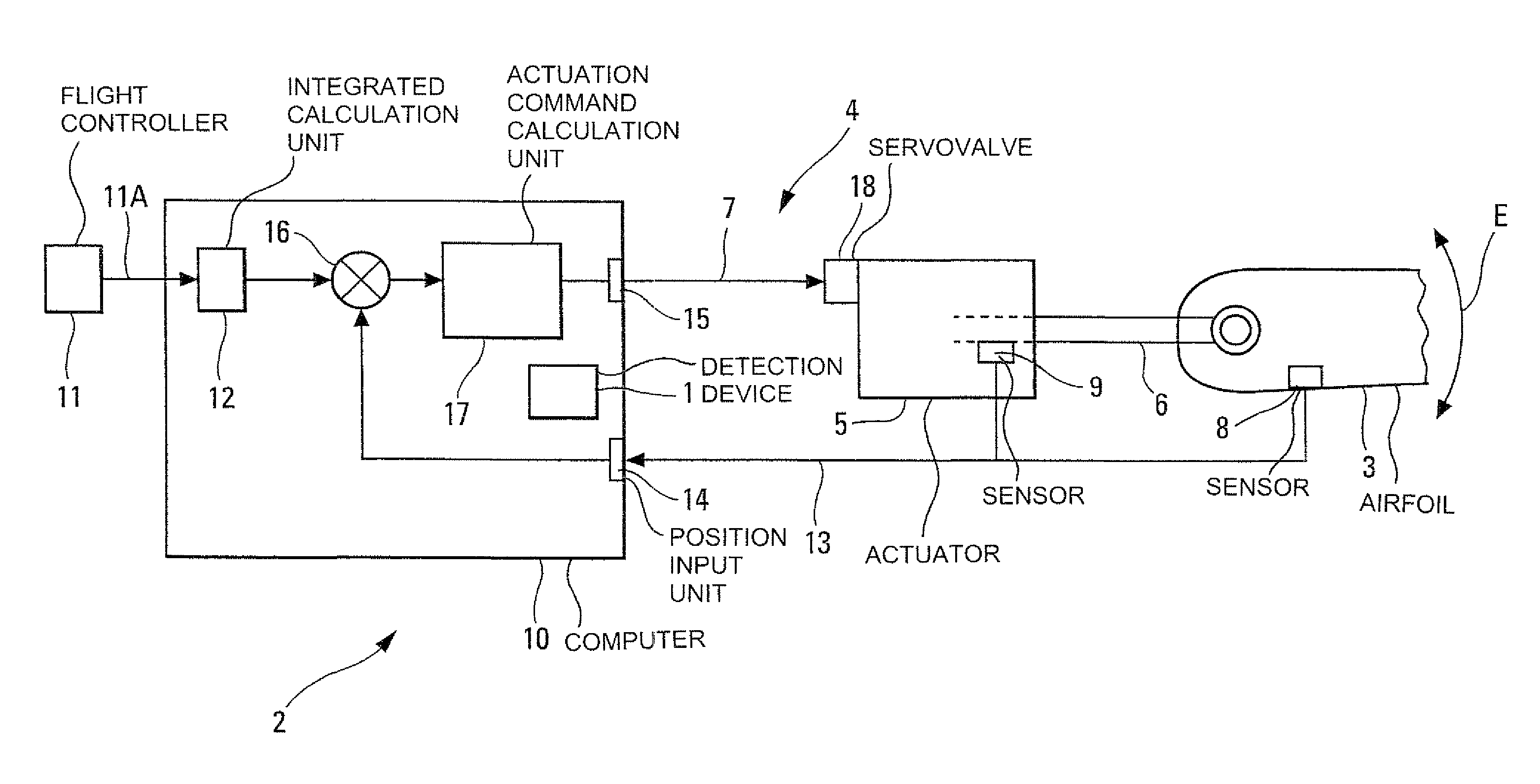
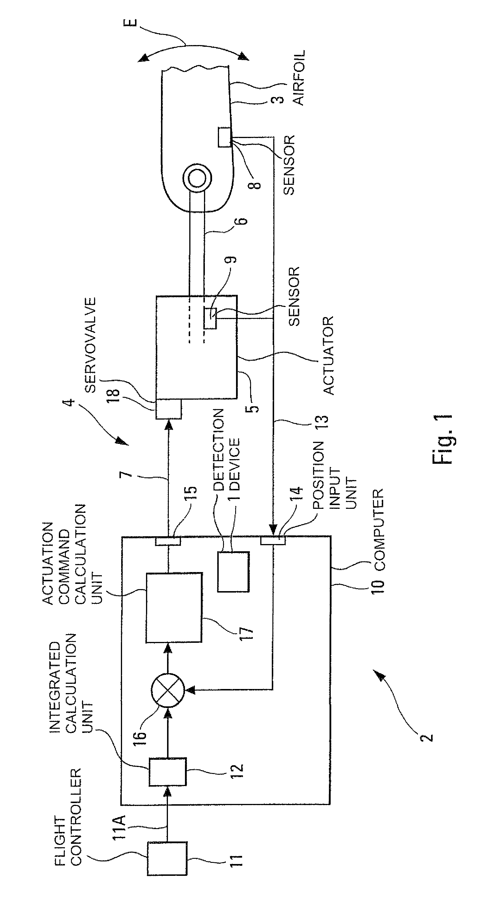
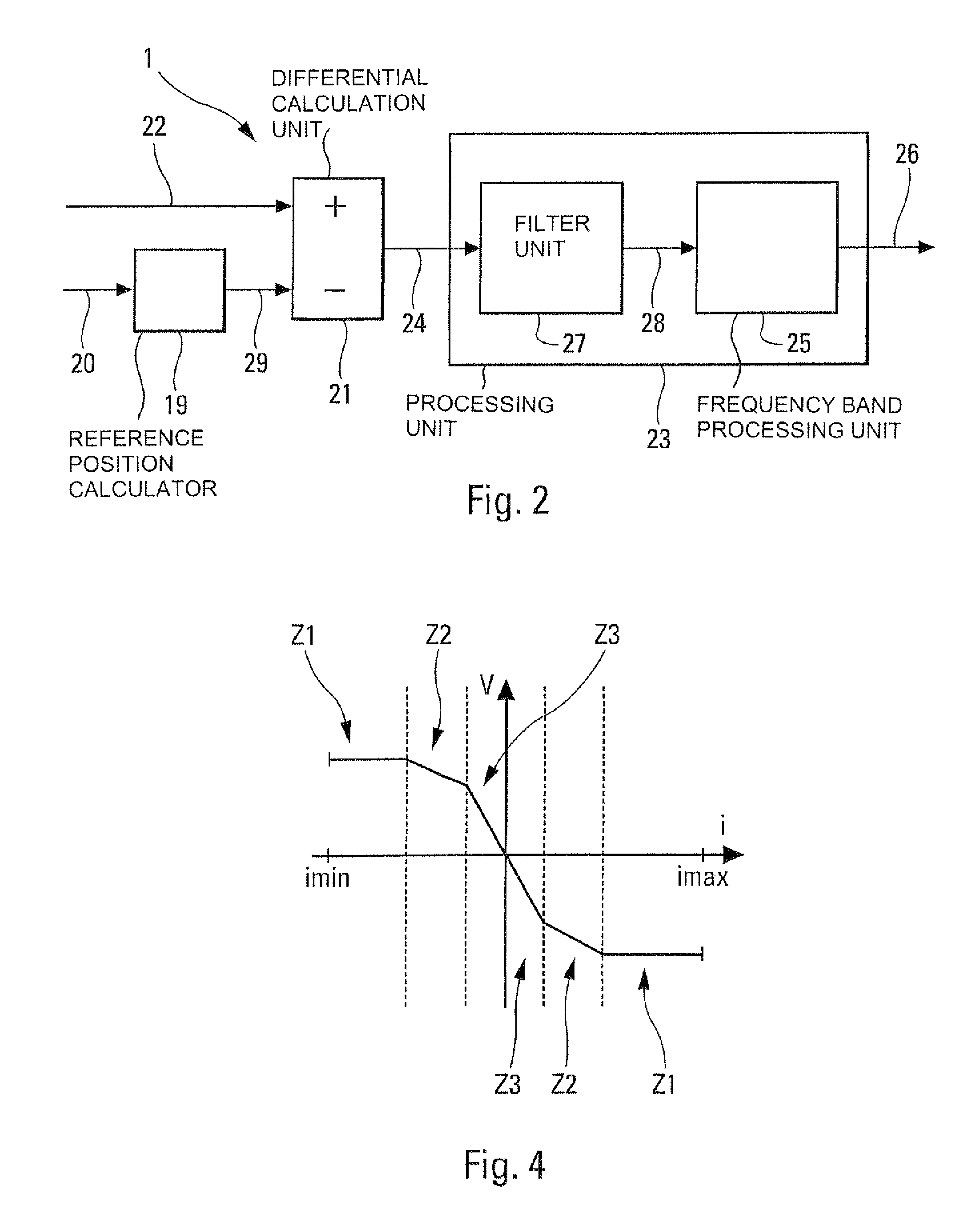
[0089]The device 1 in accordance with the invention and represented schematically in FIG. 2 is intended to detect at least one oscillatory fault in at least one positional slaving chain 2 (represented in FIG. 1) of at least one airfoil 3 (aileron, spoiler, elevator, rudder) of an aircraft, in particular of a transport airplane.

[0090]In a standard manner, this slaving chain 2 forms part of a system of electric flight controls 4 of the aircraft and comprises:[0091]said airfoil 3 which is mobile, being able to be deflected as illustrated by a double arrow E in FIG. 1, and whose position with respect to the structure of the aircraft is adjusted by at least one standard actuator 5;[0092]said actuator 5 which adjusts the position of said airfoil 3, for example by way of a rod 6 which acts on the latter, as a function of at least one actuation command received by way of a link 7;[0093]at least one sensor 8, 9 which measures the effective position of said airfoil 3. For this purpose, it may...


PUM


Abstract

Disclosed is a method of detecting at least one oscillatory fault in at least one positional slaving chain for at least one airfoil of an aircraft. The method involves estimating a reference position of the airfoil in the absence of a fault, and calculating a residual value based on the difference between the estimated reference position and the actual position measured by at least one sensor. The calculated residual value is compared with at least one predetermined threshold value to determine the number of successive and alternating overshoots of the predetermined threshold value by the residual value, and oscillatory fault is determined based on the determined number.

Description

FIELD OF THE INVENTION[0001]The present invention relates to a method and a device for detecting oscillatory faults in at least one positional slaving chain for an aircraft airfoil, as well as to a system of electric flight controls comprising such a detection device.[0002]The present invention applies to a slaving chain:[0003]which is intended to positionally slave all types of aircraft airfoil, such as ailerons, spoilers or an elevator for example;[0004]which forms part of a system of electric flight controls of the aircraft; and[0005]which comprises:[0006]said airfoil which is mobile, and whose position with respect to the aircraft is adjusted by at least one actuator;[0007]said actuator which adjusts the position of said airfoil, as a function of at least one actuation command received;[0008]at least one sensor which measures the effective position of said airfoil; and[0009]a computer which formulates an actuation command for the airfoil, transmitted to said actuator, on the bas...

Claims


Application Information

Patent Timeline
Patent Type & Authority Patents(United States)
IPC IPC(8): G01M17/00G07C5/00G06F7/00G06F19/00G06F11/30
CPCB64C13/50G05B17/02G05B23/0254
Inventor GOUPIL, PHILIPPEZOLGHADRI, ALILAVIGNE, LOIC
Owner CENT NAT DE LA RECHERCHE SCI
Why Eureka
Try Eureka