Supercharge Your Innovation With Domain-Expert AI Agents!

Power supply control method and circuit in communication equipment

a technology of communication equipment and control method, applied in the field of communication equipment, can solve the problems of reducing the value of normal operating power, the inability of information communication equipment to tolerate idle state, and the inability of information communication equipment to reduce the average power consumption, so as to achieve the effect of lowering the power consumption of a circuit devi

Active Publication Date: 2012-04-17
RAKUTEN GRP INC
View PDF10 Cites 2 Cited by
  • Summary
  • Abstract
  • Description
  • Claims
  • Application Information

AI Technical Summary

Benefits of technology

This approach effectively lowers power consumption in communication equipment without impairing performance, even with an increased number of processing sections, by optimizing power usage based on data availability and processing delays, thus addressing the limitations of existing techniques.

Problems solved by technology

Therefore, there is a premise that information communication equipment cannot tolerate the idle state, unlike electronic equipment such as computers and servers.
That is, information communication equipment has no other way of reducing the average power consumption but by lowering the value of normal operating power.
However, in reality, as to the effect of the lower operating voltage owing to a finer electronic part, the operating voltage has already fallen below one volt, and the pace of operating voltage reduction is slowing down.
Therefore, it is more and more difficult to achieve a significant reduction of power consumption in information communication equipment.
Accordingly, despite individual device venders' efforts at the device technology-based studies, the power consumption in the idle state is significantly increasing.
Accordingly, there is a problem that ordinary developers have no opportunity to use the asynchronous circuitry and schemes, as development techniques, for general electronic parts such as, for example, application specific integrated circuits (ASICs) and field programmable gate arrays (FPGAs), since development tools for design and evaluation have not been improved yet.
However, it is known that packet-based communication is not performed at all times and therefore the packet-based communication equipment may be kept in the state capable of data communication without transmitting or receiving data for a considerably long time.
Since power is supplied even when each packet processing section does not need to perform packet processing, power consumption called “standby power” is produced, which means power is constantly consumed by each packet processing section.
It is apparent that the techniques described in JP2002-182807 and JP2003-271267 cannot solve such a problem.

Method used


Image

  • Power supply control method and circuit in communication equipment
  • Power supply control method and circuit in communication equipment
  • Power supply control method and circuit in communication equipment

Examples


Embodiment Construction

1. Exemplary Embodiment

1.1) Circuit Structure

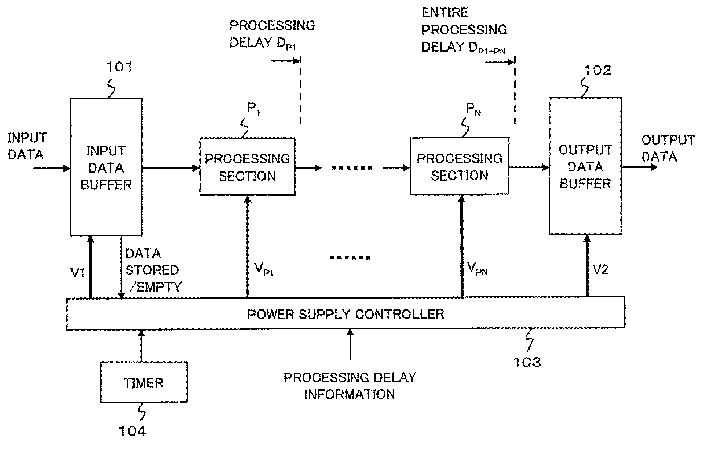
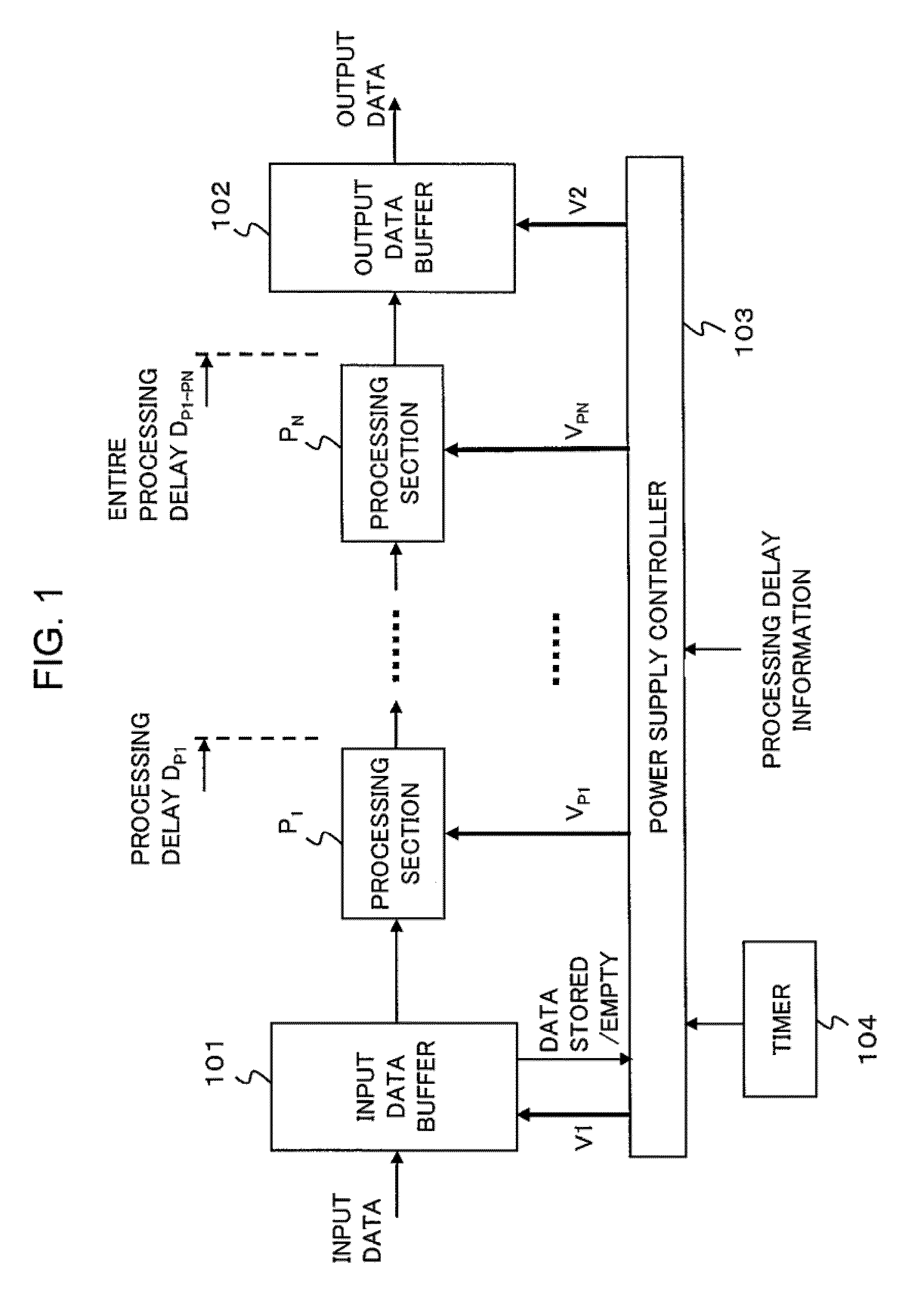
[0027]As shown in FIG. 1, a communication device includes a data processing circuit and a power supply controller which monitors the stored state of input data to control the power supply to the data processing circuit.

[0028]The data processing circuit includes an input data buffer 101, a plurality of processing sections P1-PN (N is an integer greater than 1) and an output data buffer 102. Input data is stored in the input data buffer 101 and is sequentially processed by the processing sections P1-PN. Data that has been processed by the tail-end processing section PN is stored in the output data buffer 102 and then is output as output data to a following stage. It should be noted that each of the processing sections P1-PN may perform any kind of data processing, for example, protocol processing, buffering for clock change or the like.

[0029]The power supply controller 103 according to an exemplary embodiment of the present invention output...


PUM


Abstract

A circuit includes: an input buffer for storing input data; a plurality of processing sections connected in series including a head processing section and a tail-end processing section to sequentially process the input data; and a power supply controller for controlling power supply to each of the plurality of processing sections depending on a lapse of time during which no input data is stored in the input buffer.

Description

[0001]This application is based upon and claims the benefit of priority from Japanese Patent Application No. 2008-111937, filed on Apr. 23, 2008, the disclosure of which is incorporated herein in its entirety by reference.BACKGROUND OF THE INVENTION[0002]1. Field of the Invention[0003]The present invention relates to communication equipment and, more particularly, to power supply control method and circuit for reduction of power consumption in the communication equipment such as packet-based communication equipment and the like.[0004]2. Description of the Related Art[0005]To preserve the global environment, while energy conservation measures have been considered and studied at the global level, legislation for energy conservation and carbon dioxide emissions reduction has also begun to be discussed in individual nations. Although what is generally thought of as the subject of such study and discussion is the energy consumption involved in transportation, distribution, and manufactur...

Claims


Application Information

Patent Timeline
Patent Type & Authority Patents(United States)
IPC IPC(8): G06F1/00G06F7/38G06F1/32G06F7/32H04M1/00H04L12/28G06F15/00G06F7/52H04L12/70
CPCG06F1/3209G06F1/3287H04L12/12H04L49/40Y02B60/1282Y02B60/32Y02B60/34Y02D10/00Y02D30/50
Inventor HISAMATSU, HIDENORI
Owner RAKUTEN GRP INC
Features
  • R&D
  • Intellectual Property
  • Life Sciences
  • Materials
  • Tech Scout
  • Unparalleled Data Quality
  • Higher Quality Content
  • 60% Fewer Hallucinations
Learn More