
Clogging determining device for reducing agent passage and clogging determining method for reducing agent passage

a determining device and reducing agent technology, applied in the direction of machines/engines, mechanical equipment, separation processes, etc., can solve the problems of clogging in the reducing agent supply passage, and achieve the effect of reducing the number of parts to be repaired/exchanged, accurate estimation, and efficient maintenance work

Active Publication Date: 2012-04-24
BOSCH CORP
View PDF8 Cites 24 Cited by
  • Summary
  • Abstract
  • Description
  • Claims
  • Application Information

AI Technical Summary

Benefits of technology

The solution enables efficient maintenance by accurately determining clogging in reducing agent passages, reducing the number of parts to be repaired or exchanged and minimizing NOx emissions by specifying clogged places, thus improving the overall efficiency of the exhaust gas purification process.

Problems solved by technology

Here, in the case where urea solution is used as reducing agent, hydrolysis occurs in the urea solution and thus it is crystallized when the urea solution is kept under a predetermined temperature range, so that clogging may occur in a reducing agent supply passage or an injection nozzle.

Method used


Image

  • Clogging determining device for reducing agent passage and clogging determining method for reducing agent passage
  • Clogging determining device for reducing agent passage and clogging determining method for reducing agent passage
  • Clogging determining device for reducing agent passage and clogging determining method for reducing agent passage

Examples


first embodiment

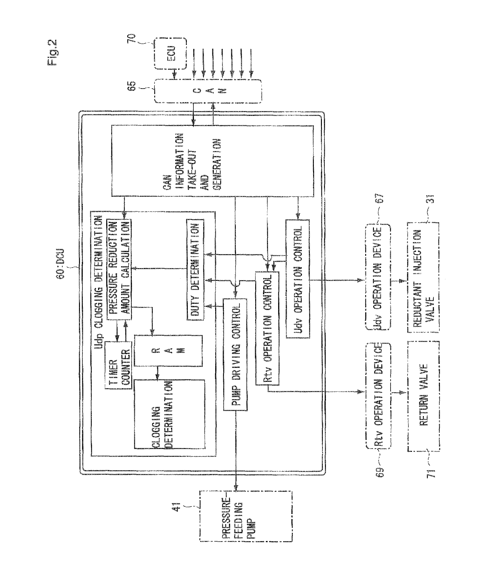
[0037]1. Clogging Determining Device for Reducing Agent Passage

[0038](1) Whole Construction of Exhaust Gas Purification System

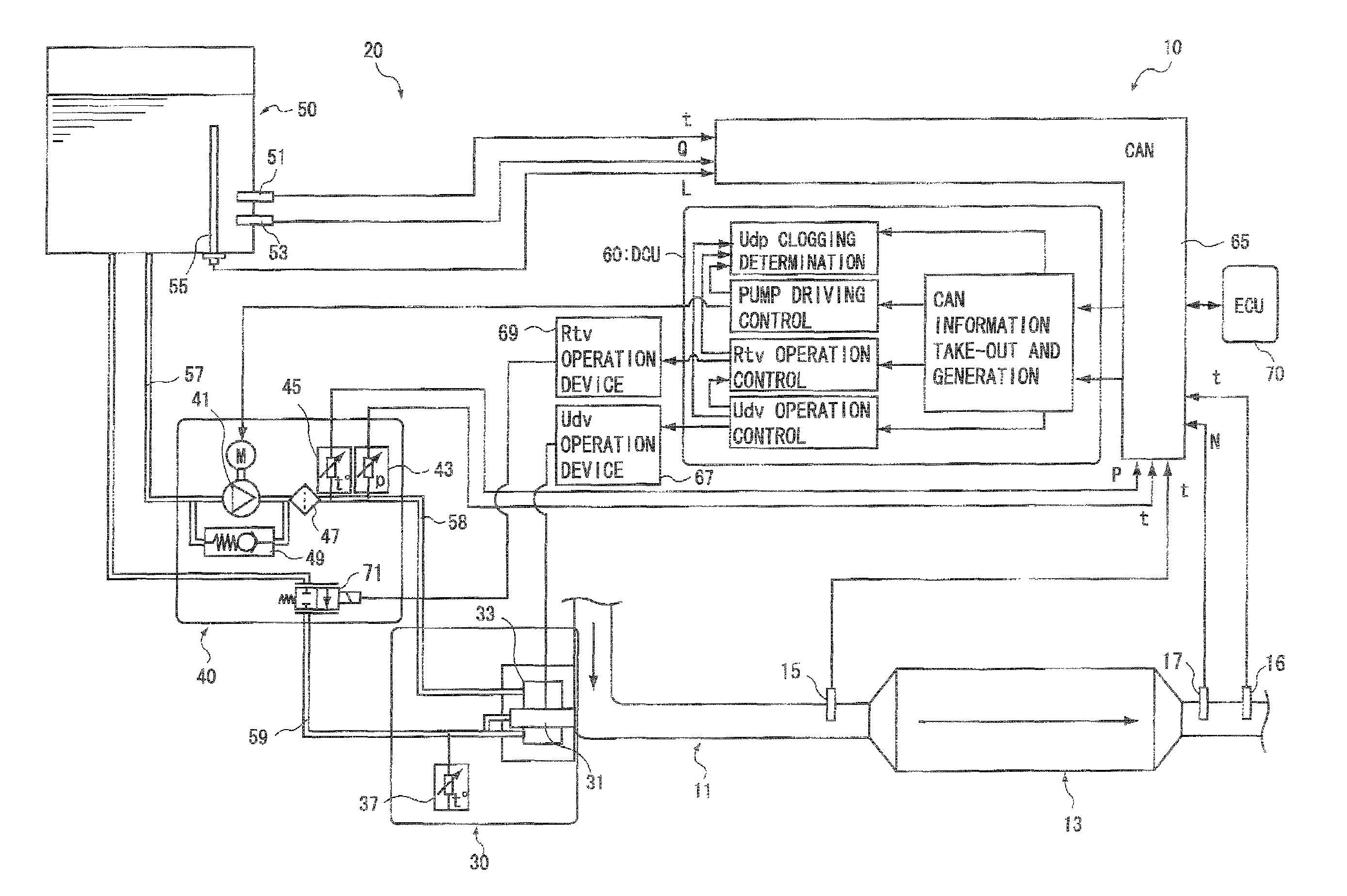
[0039]First, an example of the construction of an exhaust gas purification system having a clogging determining device for a reducing agent passage according to an embodiment (hereinafter referred to as “system” in some cases) will be described with reference to FIG. 1.

[0040]The exhaust gas purification system 10 shown in FIG. 1 is an exhaust gas purification system 10 in which urea water solution is used as reducing agent and exhaust gas is passed through NOx catalyst 13 together with the reducing agent to thereby selectively reduce NOx. This exhaust gas purification system 10 is provided with an NOx catalyst 13 for selectively reducing NOx contained in exhaust gas which is disposed at some midpoint of an exhaust gas passage 11 connected to an internal combustion engine and a reducing agent supply device 20 containing a reducing agent injection valve 31 for ...

second embodiment

[0085]1. Clogging Determining Device for Reducing Agent Passage

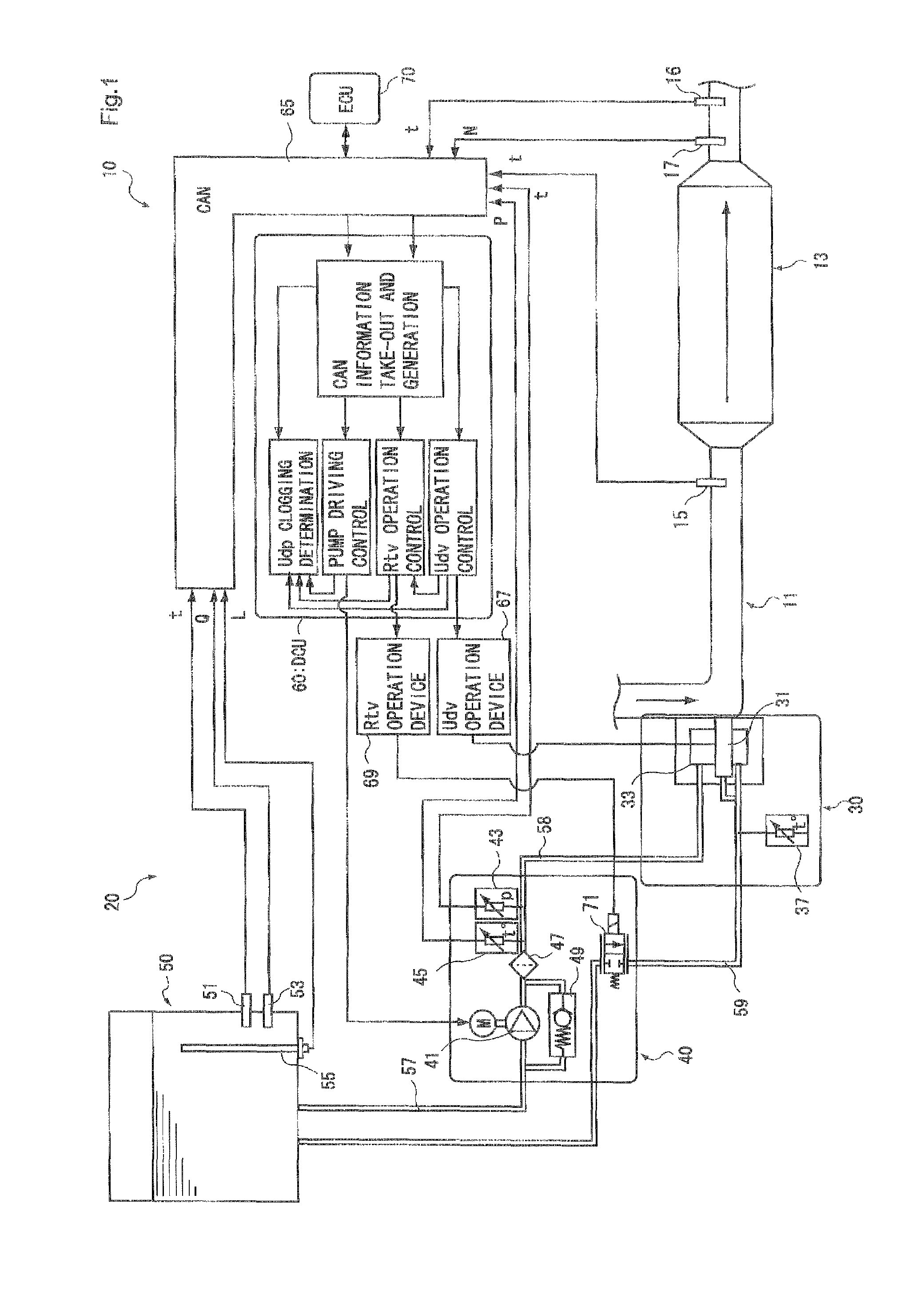
[0086]An example of the construction of an exhaust gas purification system having a clogging determining device for a reducing agent passage according to this embodiment (hereinafter referred to as “system” in some cases) is shown in FIG. 4.

[0087]The exhaust gas purification system 100 shown in FIG. 4 is constructed so that an orifice 35 is provided in place of the return valve 71 provided to the circulating passage 59 in the exhaust gas purification system 10 of the first embodiment shown in FIG. 1.

[0088]That is, the injection module 30 in the exhaust gas purification system 100 of this embodiment has a pressure chamber 33 in which reducing agent pressure-fed from the pump module 40 side is stocked, a reducing agent injection valve 31 connected to the pressure chamber 33, an orifice 35 disposed at some midpoint of a passage extending from the pressure chamber 33 and intercommunicating with a circulating passage 59, and ...

third embodiment

[0100]1. Whole Construction of Exhaust Gas Purification System

[0101]An exhaust gas purification system having a clogging determining device for a reducing agent passage according to this embodiment is different from the exhaust gas purification system of the first embodiment in the construction of the reducing agent passage of the reducing agent supply device.

[0102]FIG. 6 shows an example of the construction of the exhaust gas purification system 110 according to this embodiment, and the same constituent elements of the exhaust gas purification system of the first embodiment are used as the constituent elements other than the reducing agent supply device 120.

[0103]The reducing agent supply device 120 provided to the exhaust gas purification system 110 of this embodiment has a reducing agent injection valve 131, a storage tank 150 in which reducing agent is stocked, a pump module 140 containing a pump 141 for pressure-feeding reducing agent in the storage tank 150 to the reducing age...


PUM

PropertyMeasurementUnit
pressureaaaaaaaaaa
pressure reductionaaaaaaaaaa
temperatureaaaaaaaaaa

Abstract

There are provided a clogging determining device for a reducing agent passage and a clogging determining method for a reducing agent passage, which can accurately detect clogging and estimate a clogged place when clogging occurs in any place of a supply line or a return line.The device includes pump driving control element for subjecting the pump to DUTY control so that a pressure value is kept to a predetermined value, driving DUTY determining element for determining whether the driving DUTY of the pump is less than a predetermined threshold value corresponding to the opening degree of the reducing agent injection valve, or not; pressure reduction amount calculating element for calculating a pressure reduction amount by which the pressure value detected by the pressure sensor is reduced within a predetermined time after the pump is stopped and the reducing agent injection valve is fully opened when it is determined that the driving DUTY of the pump is less than the threshold value, and clogging determining element for determining on the basis of the pressure reduction amount calculated by the pressure reduction amount: calculating element whether clogging occurs in the first reducing agent passage or the second reducing agent passage.

Description

TECHNICAL FIELD[0001]The present invention relates to a clogging determining device for a reducing agent passage and a clogging determining method for a reducing agent passage in an exhaust gas purification system. Particularly, the present invention relates to a clogging determining device for a passage and a clogging determining method for a reducing agent passage in an exhaust gas purification system having a return passage for keeping reducing agent under low temperature.BACKGROUND ART[0002]Oxides of nitrogen (hereinafter referred to as NOx) which may risk the environment are contained in exhaust gas discharged from an internal combustion engine such as a diesel engine or the like. As an exhaust gas purification system used for purifying NOx there has been known an exhaust gas purification system (SCR system) for injecting and mixing urea solution as reducing agent into exhaust gas and selectively reducing and purifying NOx with catalyst.[0003]Here, in the case where urea soluti...

Claims


Application Information

Patent Timeline
Patent Type & Authority Patents(United States)
IPC IPC(8): F01N3/36
CPCF01N3/2066F01N11/00B01D2251/2067B01D2257/404F01N2550/05F01N2610/02F01N2610/14Y02T10/47Y02T10/24Y02T10/12Y02T10/40B01D53/86B01D53/94F01N3/04F01N3/08
Inventor KITAZAWA, EIICHI
Owner BOSCH CORP
Learn More