Foldable table for notebook-computer
a notebook computer and foldable technology, applied in the field of tables, can solve the problems of inconvenient reading or using the notebook computer in the bed, inconvenience, discomfort and insanitary, and unsuitability for carrying, and achieve the effects of convenient storage, compact and portable, and convenient us
- Summary
- Abstract
- Description
- Claims
- Application Information
AI Technical Summary
Benefits of technology
Problems solved by technology
Method used
Image
Examples
example 1
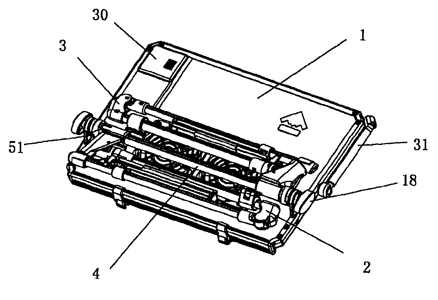
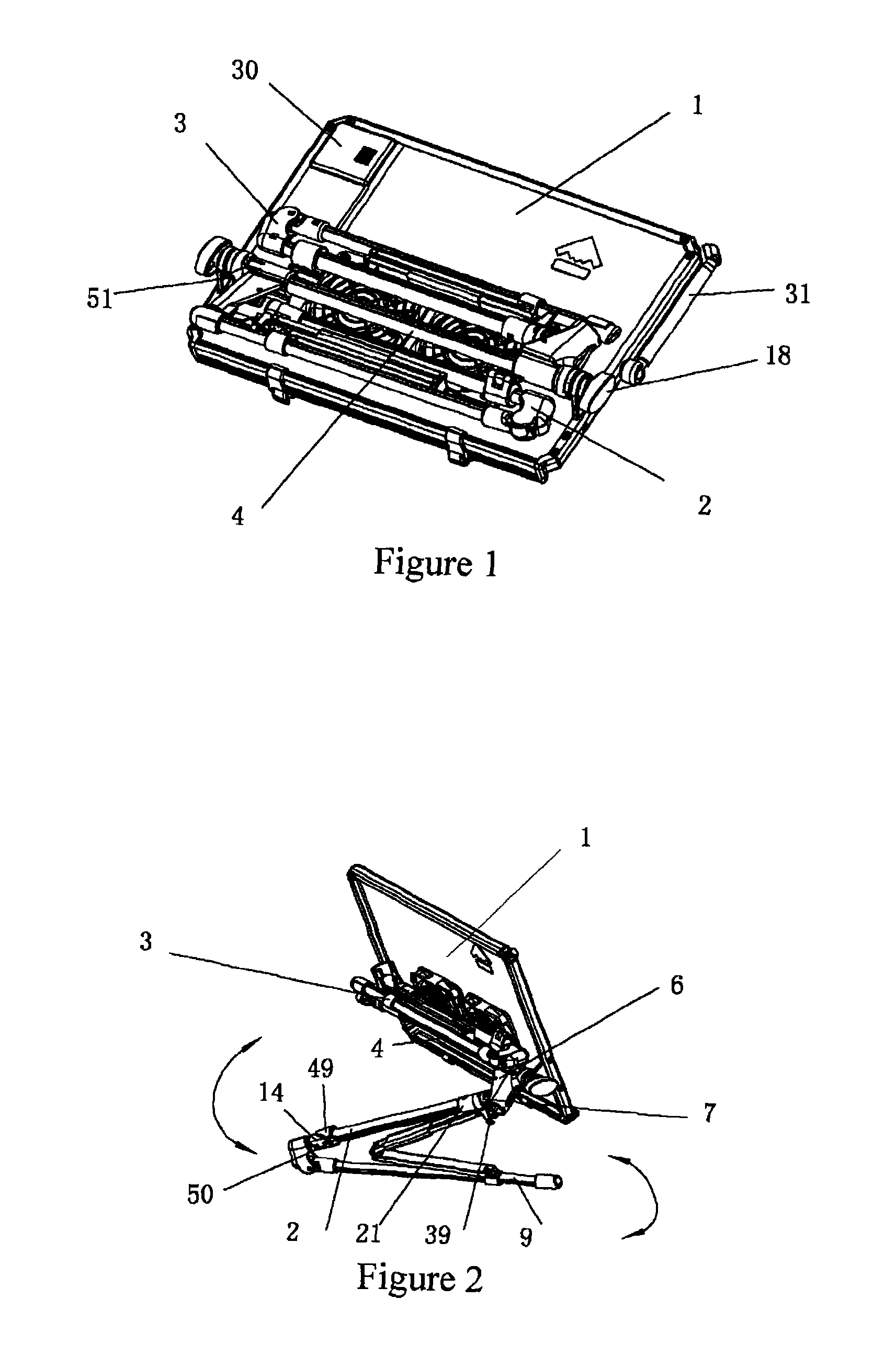
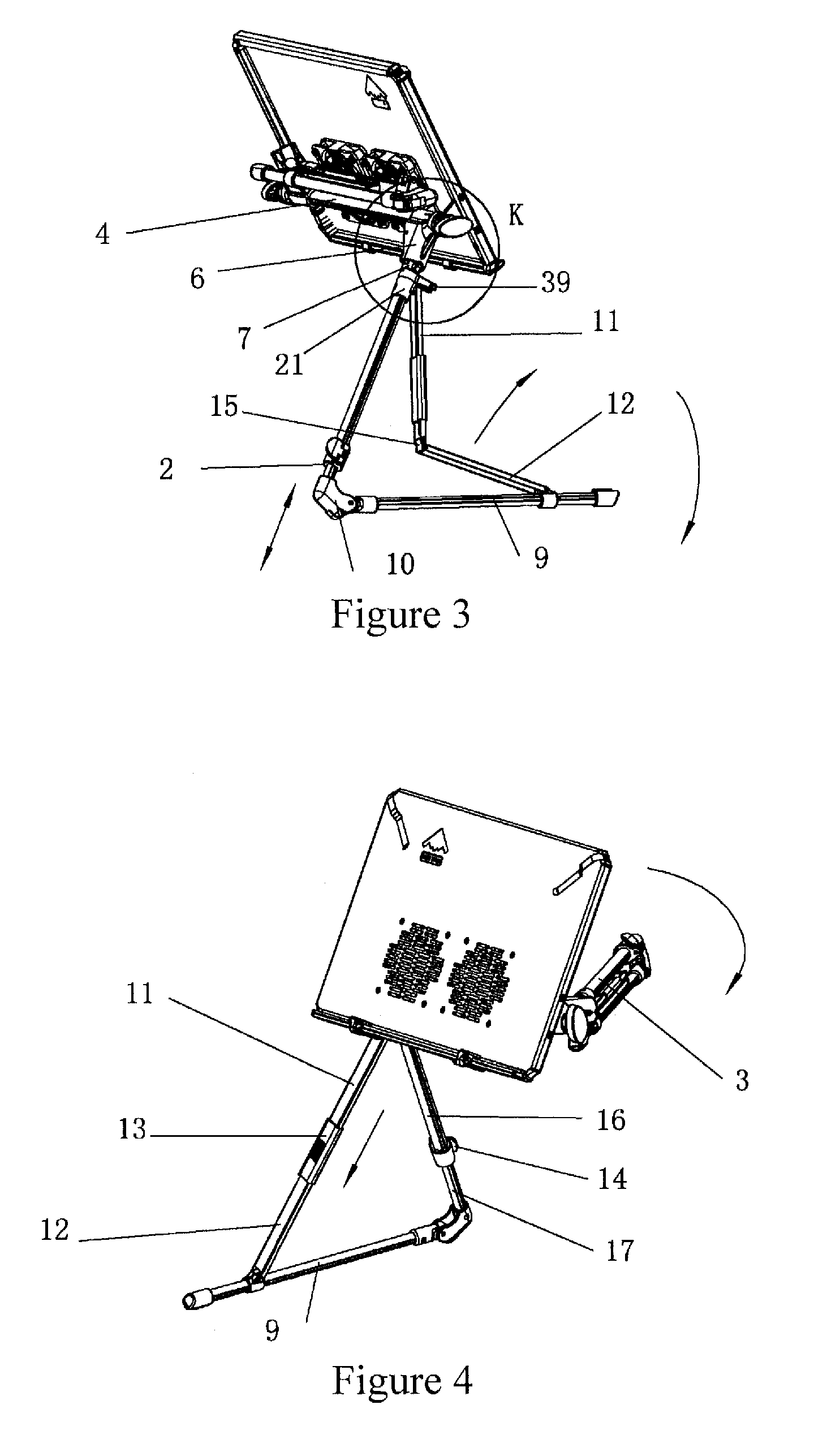
[0074]With reference to FIGS. 1 and 2, a foldable table for a notebook computer of the present example comprises a table top 1, a cross beam tube 4, a corner coupler 6 and foldable supporting frames 2, 3. The foldable supporting frames 2 and 3 are connected to the left and right ends of the cross beam tube 4, respectively, and have the identical configuration. One or more USB ports, a battery case 30 and an illuminator 31 are provided in the table top 1. Lugs 51 arranged on the left and right sides, respectively, are fixed to the table top 1. Both ends of the cross beam tube 4 are co-axially connected to the lugs 51. Knobs 18 are provided at both ends of the cross beam tube 4 and can lock the cross beam tube 4. As shown in FIGS. 2, 3, 7 and 11, angular couplers 6 are fitted to both ends of the cross beam tube 4, and a top hook connector 7 is provided on a top of the foldable supporting frame 2, so that the foldable supporting frame 2 can be rotated about a semi-circular hinge axle 8...
example 2
[0089]Referring to FIG. 16, it shows another configurations of the foldable supporting frames 2 and 3 in which the top hook coupler 7 in the above-mentioned foldable supporting frames 2 and 3 is replaced by a top hook coupler 43. The top hook coupler 43 is fixedly connected to the outer sleeving 16 directly and the connections among the spinning coupler 21, fitting spindle and end surface spring 38 are removed. As shown in FIG. 16, a column 44 provided in an angular coupler 6 engages co-axially into a hole on the section of a synchronizing handle 45. A co-axial torsional spring 47 is provided on the column 44 and provides a torque such that a left tip 48 presses the exterior peripheral of a cross beam tube 4. When an opening 46 on the cross beam tube 4 rotates to a position where the opening 46 matches the left tip 48 of the synchronization handle 45, the left tip 48 can be automatically clamped in the opening 46 of the cross beam tube 4 and locks the cross beam tube 4 in order to s...
example 3
[0090]Referring to FIG. 17, the present example simplifies the above-mentioned two examples in structure. In the present example, heat dissipating openings, a fan, a USB port or USB ports 28, a battery case 31 and a poled illuminator 31 are not included. Foldable supporting frames 2 and 3 cooperate with angular couplers 6 in a direct use of a top hook coupler. Thus, the folding manner is changed that the foldable supporting frames 2 and 3 can be folded with one folding step being omitted. Therefore, the folding process is simpler but the height of the foldable supporting frames after being folded increases lightly.
PUM
 Abstract
Description
Claims
Application Information
 - R&D
- Intellectual Property
- Life Sciences
- Materials
- Tech Scout
- Unparalleled Data Quality
- Higher Quality Content
- 60% Fewer Hallucinations
Browse by: Latest US Patents, China's latest patents, Technical Efficacy Thesaurus, Application Domain, Technology Topic, Popular Technical Reports.
© 2025 PatSnap. All rights reserved.Legal|Privacy policy|Modern Slavery Act Transparency Statement|Sitemap|About US| Contact US: help@patsnap.com


