Construction machine

a construction machine and construction technology, applied in the direction of fluid couplings, lighting and heating apparatus, couplings, etc., can solve the problems of poor cooling efficiency of the overlap with the space of the heat exchange device has become even smaller, and the heat exchange efficiency of the upstream-side heat exchanger is not good, so as to improve the cooling efficiency

Inactive Publication Date: 2012-04-24
NIHON KENKI CO LTD
View PDF18 Cites 19 Cited by
  • Summary
  • Abstract
  • Description
  • Claims
  • Application Information

AI Technical Summary

Benefits of technology

[0007]In view of the above-discussed problems with the prior art, it is an object of the present invention to provide a construction machine in which, even if heat exchangers are arranged partially overlappingly with respect to the flowing direction of the cooling air, the cooling air can be supplied actively to the heat exchangers located on the downstream side, thereby making it possible to enhance the efficiency of cooling by the heat exchangers located on the downstream side.
[0011]However, in the present invention, in the top cover which is provided on the supporting structure in such a manner as to cover upper positions of the first, second, and third heat exchangers, an upper opening is provided at a position corresponding to a clearance between the first heat exchanger and the third heat exchanger. By so doing, the upper opening is capable of supplying external cool cooling air to the clearance between the first heat exchanger and the third heat exchanger. As a result, the cool cooling air which flows in from the upper opening can be supplied to the first heat exchanger through the clearance, thereby making it possible to improve the cooling efficiency of the first heat exchanger.
[0012]Moreover, since the cool cooling air which is supplied from the upstream side is supplied to the second heat exchanger, it is possible to prevent the flow rate of the cooling air from declining due to the unnecessary intake of air. This also makes it possible to enhance the cooling efficiency of the first, second, and third heat exchangers. Moreover, three heat exchangers can be accommodated compactly in the supporting structure, and three or more heat exchangers can be mounted even on an ultra-small construction machine called a mini excavator.
[0014]By virtue of this configuration, the second heat exchanger at its upper position is covered by the fixed type cover. As for the second heat exchanger, however, since its upstream side in the flowing direction of the cooling air is open, it is possible to easily perform the inspection operation, cleaning operation, and the like. Meanwhile, as for the first heat exchanger and the third heat exchanger, since their upper positions are covered by the detachable type cover, if this detachable type cover is removed, it is possible to easily perform the inspection operation, cleaning operation, and the like through the clearance with respect to the first heat exchanger concealed in the rear of the third heat exchanger.
[0016](4) According to the present invention, the top cover is configured to be provided with a net member for dust prevention which covers the upper opening. Accordingly, it is possible to supply cooling air from which dust and the like have been removed by this net member. Hence, it is possible to prevent the first heat exchanger from becoming damaged and the dust and the like from being deposited, thereby making it possible to improve the reliability, maintenance workability, and the like.
[0017](5) According to the present invention, the supporting structure is configured to be detachably provided with a dust preventive net for capturing dust in the cooling air by being located upstream of the first, second, and third heat exchangers in the flowing direction of the cooling air. By this configuration, this dust preventive net is capable of capturing dust in the cooling air, so that cooling air with dust and the like removed therefrom can be supplied to the heat exchangers. When the dust preventive net is removed, the dust and the like attached to this dust preventive net can be easily cleaned away. Further, with the dust preventive net removed, the first, second, and third heat exchangers can be exposed, making it possible to perform the inspection operation, cleaning operation, and the like thereof.

Problems solved by technology

Meanwhile, in cases where the number of heat exchangers has increased or the installation space of the heat exchange device has become even smaller, not all the heat exchangers can be disposed in parallel.
For this reason, there is a problem in that, among the downstream-side heat exchangers, those portions that overlap with the upstream-side heat exchanger are poor in the cooling efficiency.

Method used


Image

  • Construction machine
  • Construction machine
  • Construction machine

Examples


Embodiment Construction

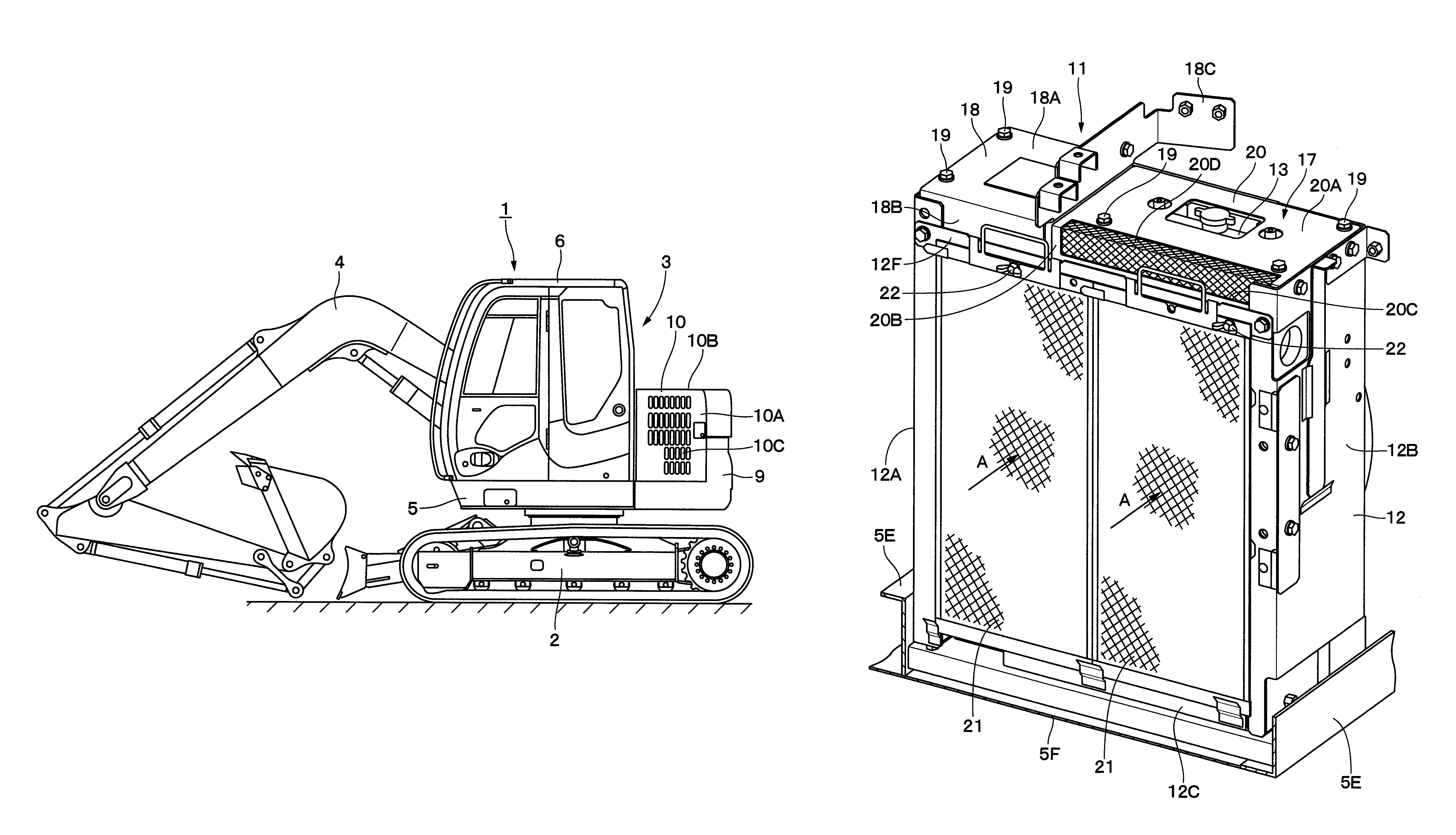
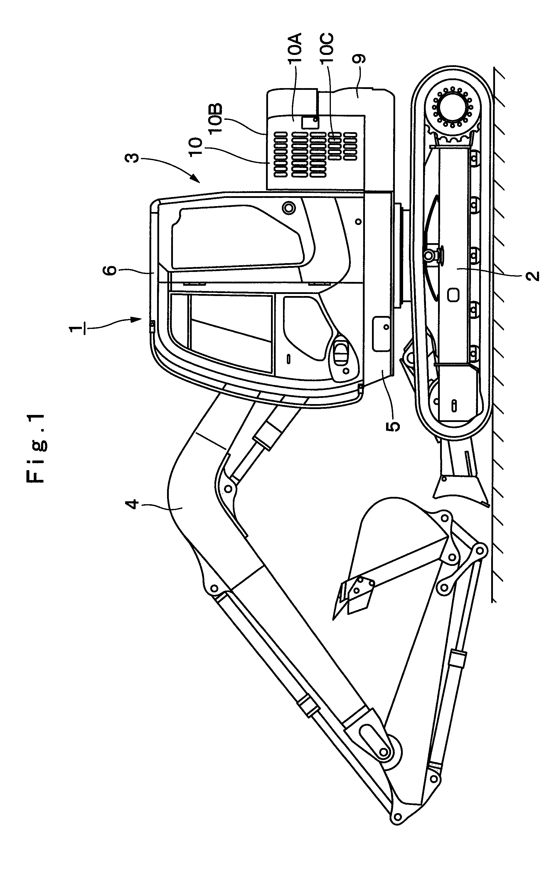
[0059]Hereafter, with reference to FIGS. 1 to 8, a detailed description will be given by citing as an example a crawler type hydraulic excavator as a construction machine in accordance with an embodiment of the present invention.

[0060]In FIG. 1, designated at 1 is a crawler type hydraulic excavator as a construction machine, and the hydraulic excavator 1 is largely constituted by an automotive lower traveling structure 2, an upper revolving structure 3 which is swingably mounted on the lower traveling structure 2 and constitutes a vehicle body together with the lower traveling structure 2, and a working mechanism 4 liftably mounted on the front side of the upper revolving structure 3 to perform the operation of such as excavating earth and sand.

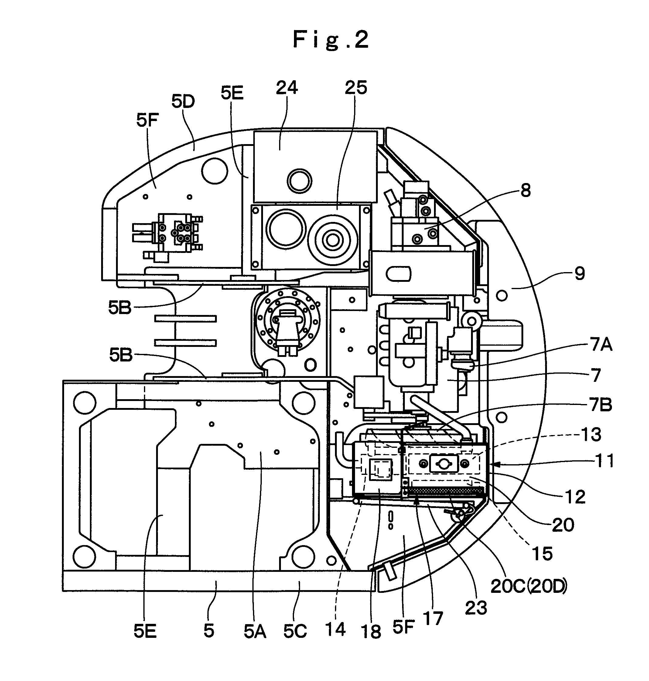
[0061]Designated at 5 is a revolving frame which constitutes the upper revolving structure 3, and the revolving frame 5 is formed as a supporting structure. Further, as shown in FIG. 2, the revolving frame 5 is largely constituted by a bottom...


PUM


Abstract

A top cover (17) is provided at an upper position of a supporting structure (12) of heat exchange device (11), and an upper opening (20C) is configured to be provided in a detachable type cover (20) for constituting this top cover (17) at a position corresponding to a clearance (16) between a radiator (13) and an intercooler (15) which overlap in the flowing direction (A) of cooling air. Accordingly, when a cooling fan (7B) is rotatively driven, the upper opening (20C) allows cool cooling air to flow into the supporting structure (12) and to be supplied to the radiator (13) through the clearance (16) between the radiator (13) and the intercooler (15). As a result, only the radiator (13) which overlaps with the intercooler (15) can be efficiently cooled by the cool cooling air from the upper opening (20C).

Description

TECHNICAL FIELD[0001]The present invention relates to a construction machine which is used as, for example, a hydraulic excavator, a hydraulic crane, a dump truck, a lift truck, a bulldozer, or the like.BACKGROUND ART[0002]Generally, a hydraulic excavator is known as a typical example of construction machines, and this hydraulic excavator is constituted by an automotive lower traveling structure, an upper revolving structure which is swingably mounted on the lower traveling structure, and a working mechanism liftably mounted on the front side of the upper revolving structure.[0003]The upper revolving structure is largely constituted by a revolving frame serving as a supporting structure, a cab which is provided on the front side of the revolving frame and in which an operator rides, an engine which is mounted on the rear side of the revolving frame to drive a hydraulic pump, heat exchange device provided in the vicinity of the engine, and an exterior cover for covering the engine, t...

Claims


Application Information

Patent Timeline
Patent Type & Authority Patents(United States)
IPC IPC(8): B60K11/04B60H1/00F28D1/00
CPCB60K11/08E02F9/00E02F9/0866E02F9/0891F01P3/18F01P11/10F01P11/12F01P2003/187
Inventor KOBAYASHI, TAMIOMATSUSHITA, MAKOTO
Owner NIHON KENKI CO LTD
Why Eureka
Try Eureka