Safety cabinet
a biohazard and safety technology, applied in the direction of isotope separation, dispersed particle filtration, combinatorial devices, etc., can solve the problems of limited hand movement range in the working space, and the treatment is difficult for workers of low body height, and achieve the effect of convenient us
- Summary
- Abstract
- Description
- Claims
- Application Information
AI Technical Summary
Benefits of technology
Problems solved by technology
Method used
Image
Examples
embodiment 1
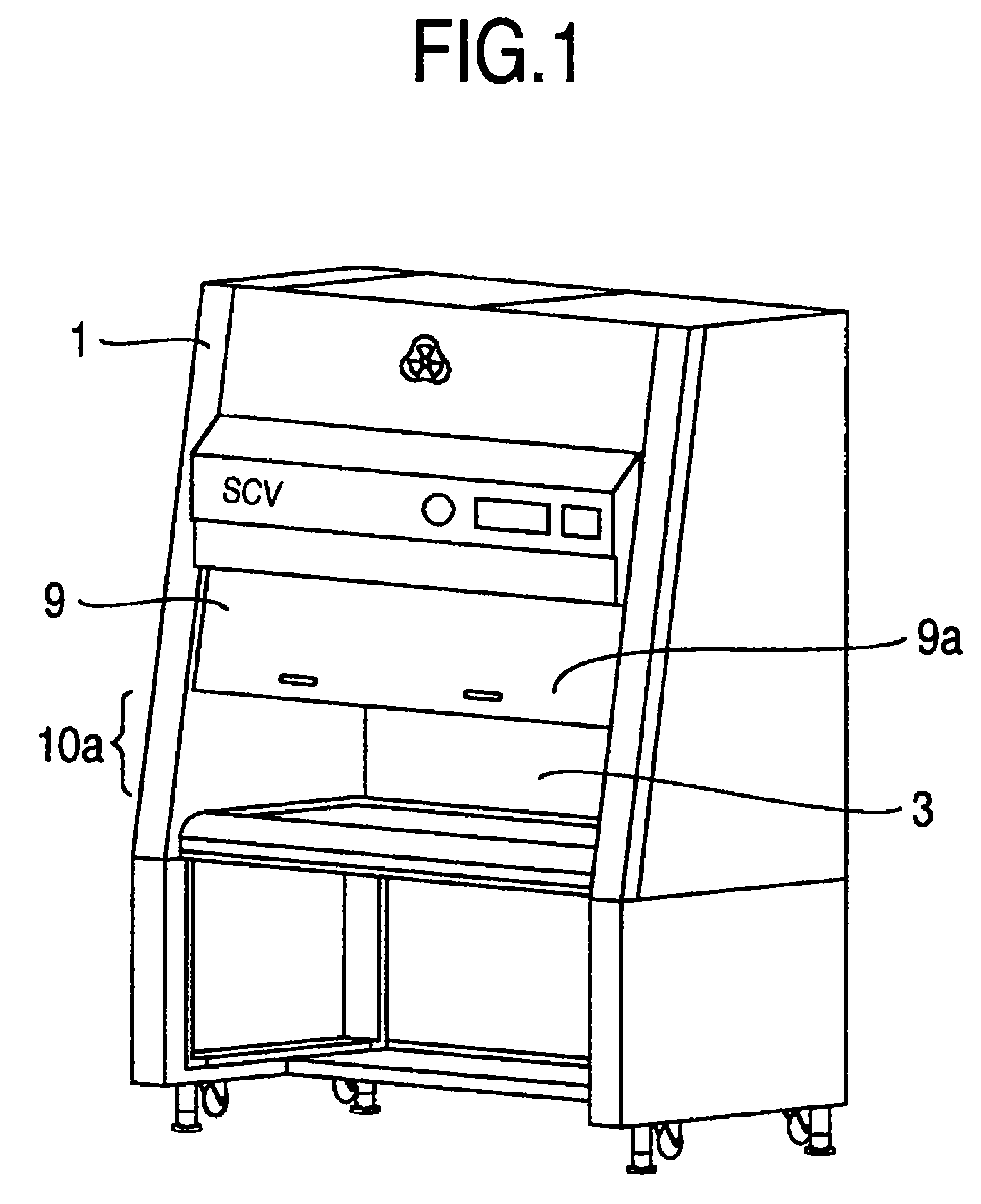
[0027]FIG. 1 is a schematic oblique projection view showing a safety cabinet as a first embodiment of the invention.
[0028]A worker extends his or her arm into a safety cabinet 1 through a front opening 10, and looks into a working space 3 through a front surface shutter 9 to treat bacteria or virus.
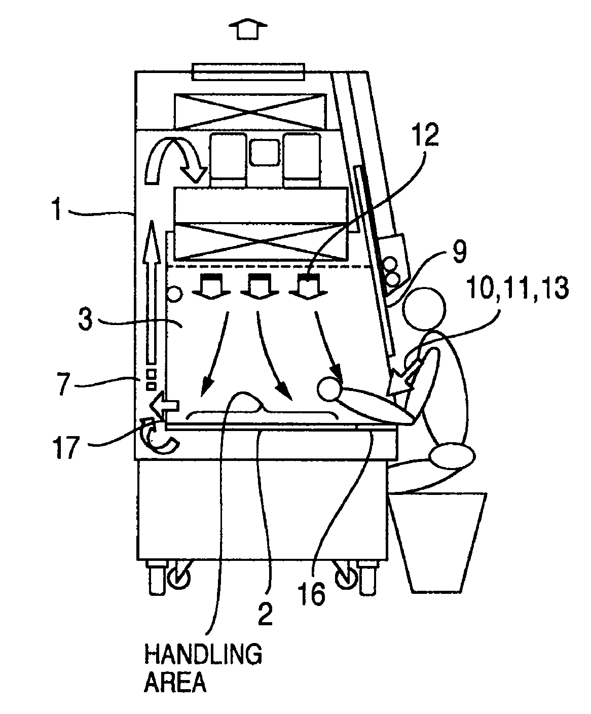
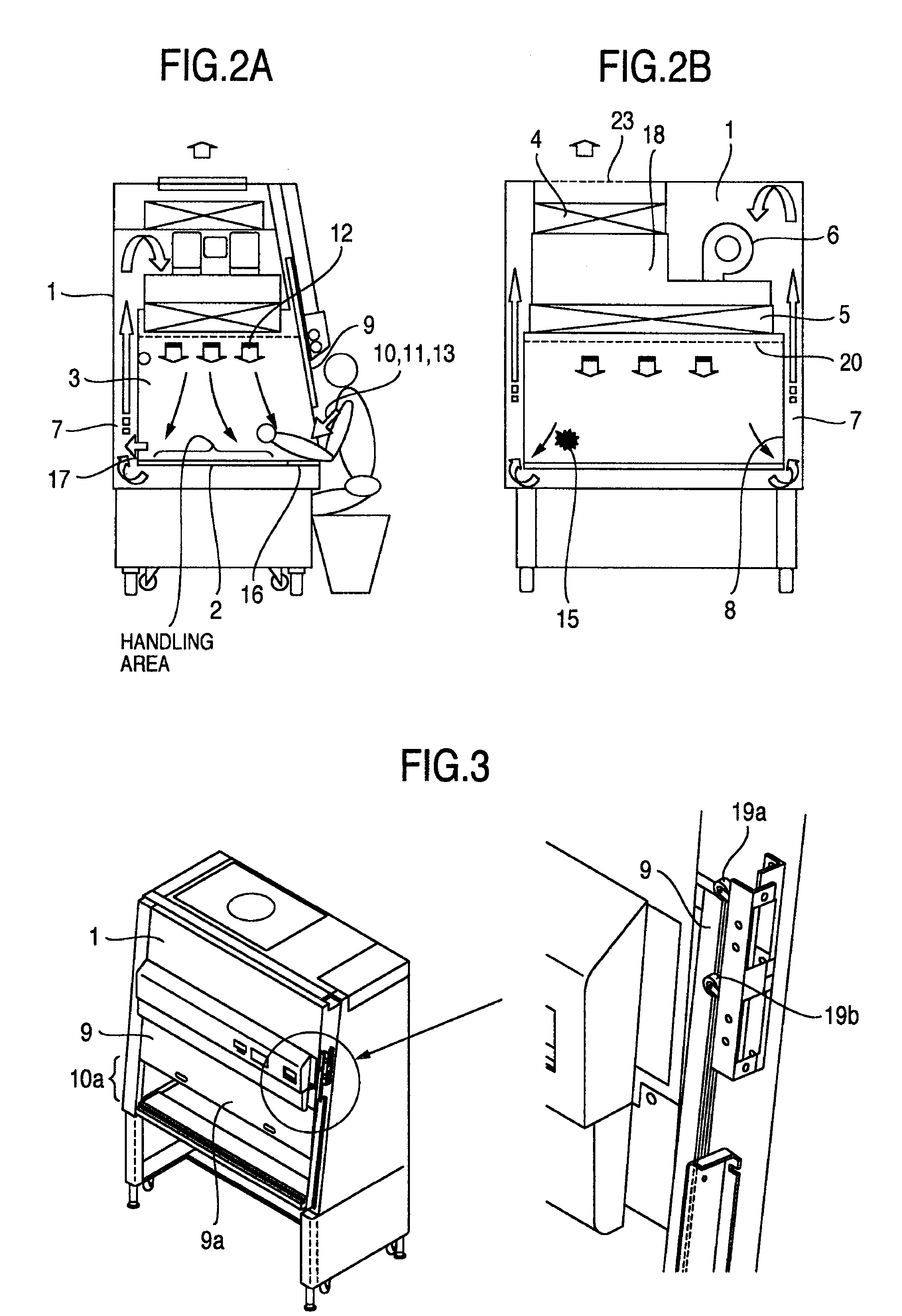
[0029]FIG. 2A is a partially cross sectional view showing the safety cabinet as the first embodiment of the invention. FIG. 2B is another partially cross sectional view showing the safety cabinet as the first embodiment of the invention.
[0030]A clean air is supplied from a HEPA filter 5 into the working space 3 of the safety cabinet 1 through a straightening vane 20.
[0031]An air 13 taken through the front opening into the safety cabinet flows to a blower 6 through a circulating path extending under a working table 2 and a back side of the working space 3. The air taken into the blower 6 is pressurized in a pressure chamber 18. The pressure chamber 18 communicates with a HEPA filter 4 for ...
embodiment 2
[0045]FIG. 4A is a partially cross sectional view showing the safety cabinet as a second embodiment of the invention, and FIG. 4B is another partially cross sectional view showing the safety cabinet as the second embodiment of the invention while FIG. 1 shows the schematic view of the safety cabinet 1.
[0046]A damper 25 is arranged in a pressure chamber 18. The air output from the blower 6 is pressurized in the pressure chamber 18. The HEPA filter 4 for discharging the air and the HEPA filter 5 for supplying the air communicate with the pressure chamber 18 so that the air is distributed between a exhaust port 23 and the working space 3. The damper 25 is arranged in the pressure chamber 18 to adjust the air toward the HEPA filter 4 for discharging the air. When the damper 25 is opened, a flow rate toward the HEPA filter 4 is increased, and when the damper 25 is closed a flow rate toward the HEPA filter 5 for supplying the air is increased. In accordance with the size 10a of the front ...
embodiment 3
[0054]FIG. 5A is a partially cross sectional view showing the safety cabinet as a second embodiment of the invention, and FIG. 5B is another partially cross sectional view showing the safety cabinet as the second embodiment of the invention while FIG. 1 shows the schematic view of the safety cabinet 1.
[0055]An intake slit damper 21 to be driven by an actuator for changing an opening area of the front intake slit 16 is arranged. By opening the intake slit damper 21, a flow rate of the air taken into the front opening 10=a flow rate of the air discharged from the exhaust port 23 is increased, and by closing the intake slit damper 21, the flow rate of the air taken into the front opening 10 is decreased. In such structure, the flow rate of the air taken into the front opening 10 is controlled in accordance with ON / OFF signal of the limit switch 19 for detecting the position of the front surface shutter 9.
[0056]Table 4 shows an example of control in the third embodiment.
[0057]
TABLE 4Fro...
PUM
| Property | Measurement | Unit |
|---|---|---|
| size | aaaaa | aaaaa |
| size | aaaaa | aaaaa |
| size | aaaaa | aaaaa |
Abstract
Description
Claims
Application Information
 - R&D
- Intellectual Property
- Life Sciences
- Materials
- Tech Scout
- Unparalleled Data Quality
- Higher Quality Content
- 60% Fewer Hallucinations
Browse by: Latest US Patents, China's latest patents, Technical Efficacy Thesaurus, Application Domain, Technology Topic, Popular Technical Reports.
© 2025 PatSnap. All rights reserved.Legal|Privacy policy|Modern Slavery Act Transparency Statement|Sitemap|About US| Contact US: help@patsnap.com


