Signal modulator

a signal modulator and signal technology, applied in the field of pulse generators and signal modulators, can solve the problems of difficult to ensure a good short pulse property, low on/off ratio, transient characteristics, etc., and achieve the effect of easy adjustment of output power and control of transmission power

Active Publication Date: 2012-04-24
PANASONIC CORP
View PDF6 Cites 6 Cited by
  • Summary
  • Abstract
  • Description
  • Claims
  • Application Information

AI Technical Summary

Benefits of technology

[0014]In view of the circumstances described above, it is an object of the invention to provide a signal modulator that can control transmission power if level adjustment of a continuous signal from an oscillator is executed.
[0032]For example, the circuit is a pulse generator for generating a pulse signal based on a continuous signal output from an oscillator and includes a control signal generator that outputs a first control signal containing an on interval and an off interval different in voltage value from the on interval in a time axis; an intermittent multiplier that receives inputs of the first control signal and the continuous signal and multiplies the continuous signal corresponding to the on interval of the first control signal to output the pulse signal; and a control section that detects a level of the pulse signal to generate a second control signal for controlling a level of the continuous signal output from the oscillator and a third control signal for controlling a conversion gain of the intermittent multiplier, wherein the conversion gain of the intermittent multiplier at the on interval of the first control signal is higher than the conversion gain of the intermittent multiplier at the off interval of the first control signal, so that a short pulse generator that can generate a pulse signal at a high on / off ratio and can easily adjust output power can be realized.
[0033]For example, the circuit includes a control signal generator that generates a first control signal containing an on interval and an off interval different in voltage value from the on interval in a time axis; a voltage controlled oscillator that outputs a modulation signal subjected to a frequency modulation based on the first control signal; and a control section that detects a level of the modulation signal to generate a second control signal for controlling a level of the modulation signal output from the voltage controlled oscillator and a third control signal for controlling a voltage level of a voltage control terminal of the voltage controlled oscillator, so that the bias voltage applied to the voltage control terminal of the voltage controlled oscillator is controlled, whereby a frequency modulation circuit including the power control function can be easily realized.

Problems solved by technology

However, the signal from the oscillator 1201 leaks when it is off and thus there is a problem in that the on / off ratio is low (refer to Non-patent Document 1).
However, the transient characteristic of the pulse signal 1501 is degraded because of operation delay at the operation start time of the oscillator and it is difficult to ensure a good short pulse property (refer to Patent Document 1).
In the related art using the mixer (FIG. 12, FIG. 13), it is difficult to realize a high on / off ratio.
In the related art using the intermittent oscillator (Non-patent Document 1), it is difficult to ensure a good short pulse property.
Usually, to realize frequency modulation communications, a circuit for performing quadrature modulation is formed, but there is a disadvantage in that the circuit configuration is complicated.

Method used


Image

  • Signal modulator
  • Signal modulator
  • Signal modulator

Examples


first embodiment

[0112](First Embodiment)

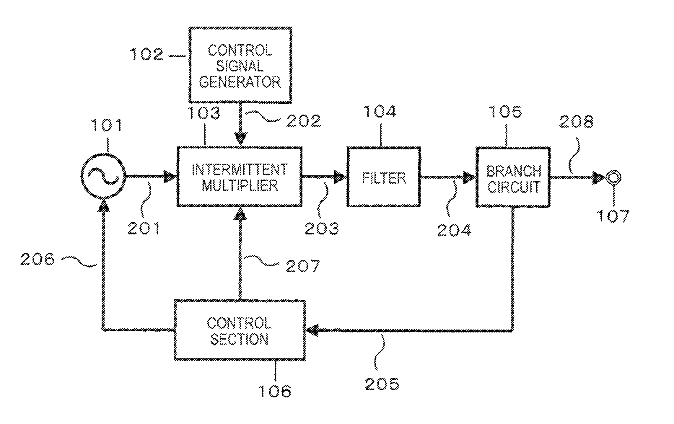
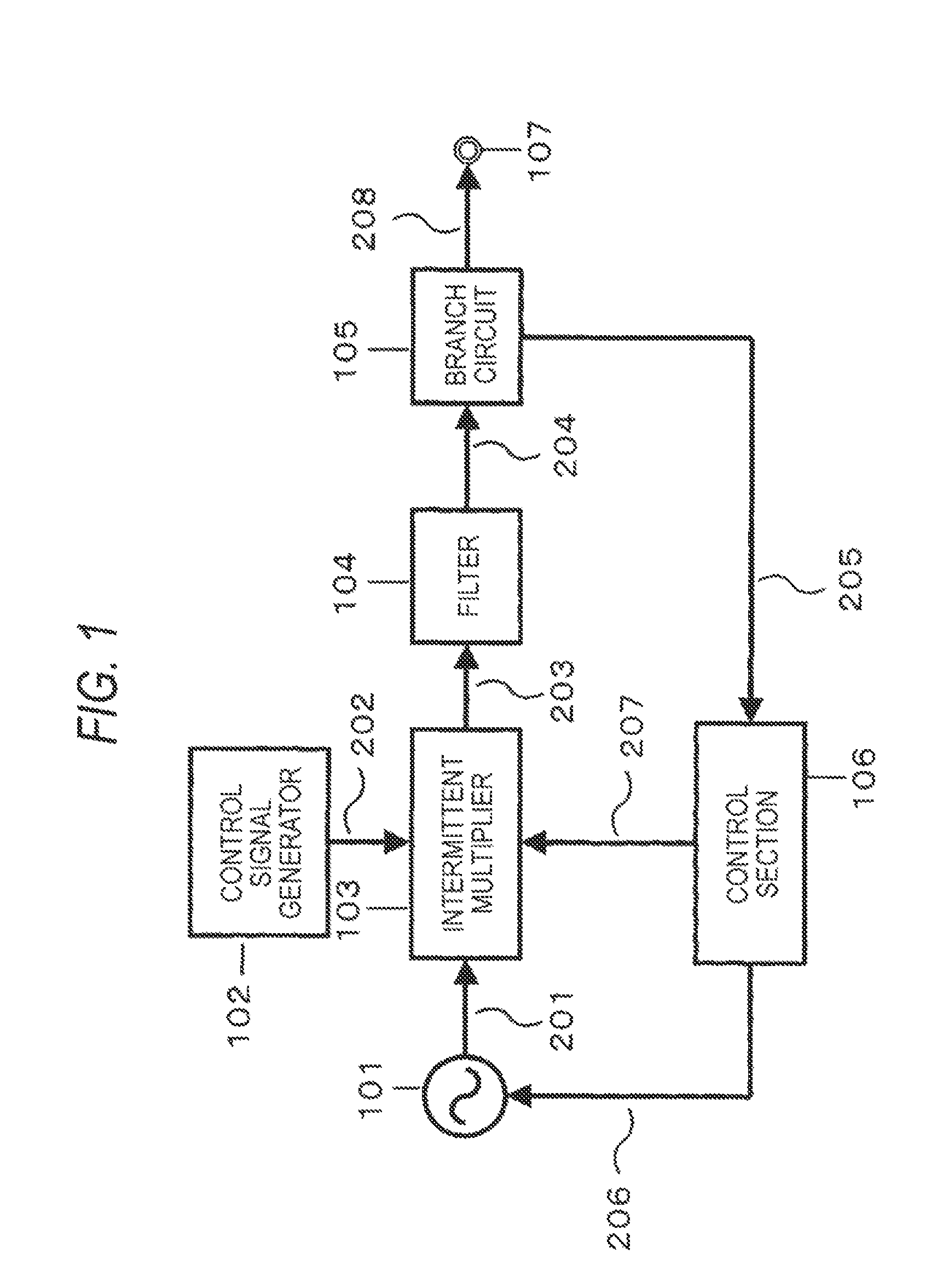
[0113]FIG. 1 is a block diagram of a communication apparatus in a first embodiment of the invention. A transmitter shown in FIG. 1 includes an oscillator 101, a control signal generator 102, an intermittent multiplier 103, a filter 104, and a branch circuit 105, a control section 106, and an output terminal 107. The oscillator 101 and the intermittent multiplier 103 are active circuits formed of active elements.

[0114]Hereinafter, the active element will be discussed as FET (field effect transistor). The multiplication number of the intermittent multiplier is n (n: A positive integer). In the description to follow, desired frequency of an output signal of the oscillator is f0, and the intermittent multiplier is a 2 multiplier (double). The signal waveform of a control signal output from the control signal generator 102 is arbitrary, but hereinafter will be discussed as a pulse waveform.

[0115]A continuous signal is output from the oscillator 101 and is input to...

second embodiment

[0173](Second Embodiment)

[0174]FIG. 10 is a block diagram to show the configuration of a pulse generator that can generate a pulse signal at a high on / off ratio and can adjust the power level in a second embodiment of the invention. The second embodiment differs from the first embodiment in that a switch 1001 is provided in place of the branch circuit 105 and the control section 106 includes a detector 1002 and a control section 1003.

[0175]The configuration shown in FIG. 10 is a transmitter-receiver. A transmitter includes an oscillator 101, a control signal generator 102, an intermittent multiplier 103, and a filter 104. A receiver includes the detector 1002 and the control section 1003. The transmitter and the receiver are connected by the switch 1001. The control section 1003 controls the oscillator 101 and the intermittent multiplier 103 based on the waveform detected by the detector 1002 included in the receiver. The control method is as described in the first embodiment.

[0176]...

third embodiment

[0181](Third Embodiment)

[0182]FIG. 11 is a block diagram to show the configuration of a pulse generator that can generate a pulse signal at a high on / off ratio and can adjust the power level in a third embodiment of the invention. The third embodiment differs from the first embodiment in that a switch 1001 is provided in place of the branch circuit 105, the control section 106 includes a mixer 1101 and a control section 1102, and an intermittent multiplier 103 is provided between an oscillator 101 and the mixer 1101 for operating the mixer. As the intermittent multiplier 103, a known circuit is used.

[0183]The configuration shown in FIG. 11 is a transmitter-receiver as with the second embodiment. A transmitter includes an oscillator 101, a control signal generator 102, an intermittent multiplier 103, and a filter 104. A receiver includes the mixer 1101 and the control section 1102. The transmitter and the receiver are connected by the switch 1001. The control section 1102 controls th...


PUM


Abstract

A signal modulator that can control transmission power if level adjustment of a continuous signal from an oscillator is executed is provided. A pulse generator of one example of a signal modulator includes an oscillator, a control signal generator, a multiplier, a filter, and a control section. The oscillator and the multiplier are active circuits formed of active elements. A continuous signal is output from the oscillator and is input to the multiplier and the multiplier intermittently operates by a control signal output from the control signal generator, whereby a pulse signal is generated and the power level is easily adjusted by a signal from the control section.

Description

TECHNICAL FIELD[0001]This invention relates to a pulse generator and a signal modulator and a transmitter in wireless communications such as a frequency modulation circuit and in particular to a signal modulator and a transmitter having a function of adjusting output power.BACKGROUND ART[0002]A pulse communication technology exists as one system of communication technology. In the pulse communication technology, system performance depends on how a pulse signal is generated. To make a pulse signal a signal having a component only of any desired frequency band, a method of limiting the frequency band of a pulse signal through a filter and extracting a specific frequency component, a method of intermittently operating an oscillator by a pulse-like control signal, and a method of inputting a pulse-like control signal to a mixer and curtaining a carrier signal, thereby generating a pulse signal exist.[0003]For the pulse generators, required performance includes a short pulse property and...

Claims


Application Information

Patent Timeline
Patent Type & Authority Patents(United States)
IPC IPC(8): H03K7/00
CPCH03C1/36H03C5/00H03K7/06H04L27/12
Inventor KOBAYASHI, SHIGERUMATSUO, MICHIAKISATO, JUNJI
Owner PANASONIC CORP
Why Eureka
Try Eureka