Audio output apparatus and audio output method
a technology of audio output and audio output, which is applied in the direction of transducer casing/cabinet/support, frequency response correction, electrical transducer, etc., can solve the problems of difficult to ensure a comfortable listening environment, and achieve the effect of small signal level and boost the low frequency
- Summary
- Abstract
- Description
- Claims
- Application Information
AI Technical Summary
Benefits of technology
Problems solved by technology
Method used
Image
Examples
first embodiment
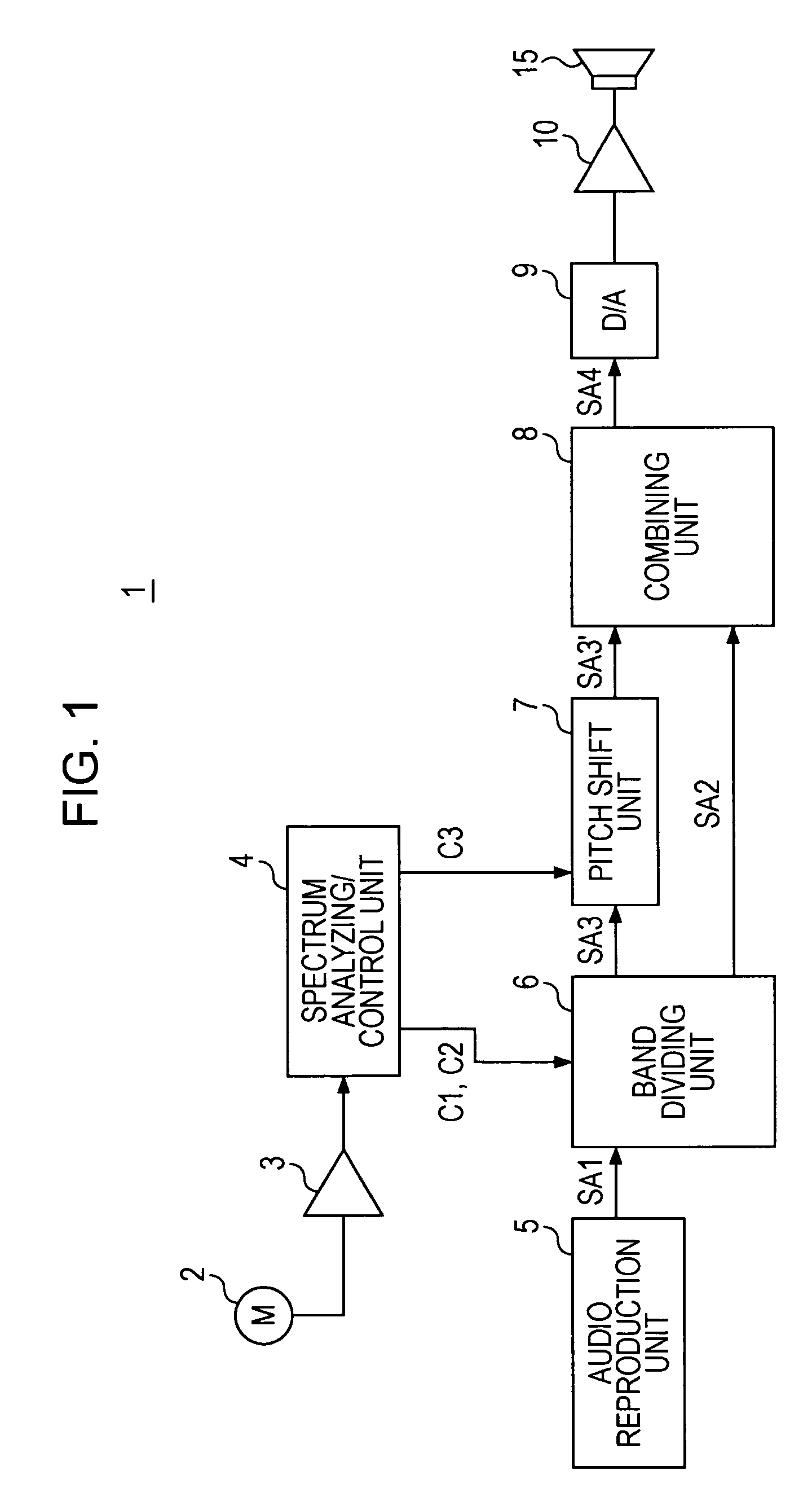
[0036]FIG. 1 illustrates an in-vehicle audio apparatus 1 according to the first embodiment of the present invention.
[0037]The audio apparatus 1 includes a microphone 2, a microphone amplifier 3, a spectrum analysis / control unit 4, an audio reproduction unit 5, a band dividing unit 6, a pitch shift unit 7, a combining unit 8, a D / A converter 9, a power amplifier 10, and a speaker 15.
[0038]The microphone 2 is used to collect noise sensible inside the vehicle, i.e., road noise, and is installed in an appropriate location inside an automobile.
[0039]Noise audio signals acquired by the microphone 2 are supplied to the spectrum analysis / control unit 4 via the microphone amplifier 3.
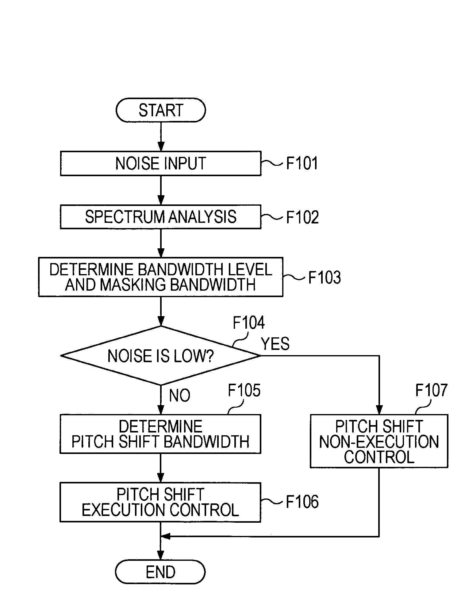
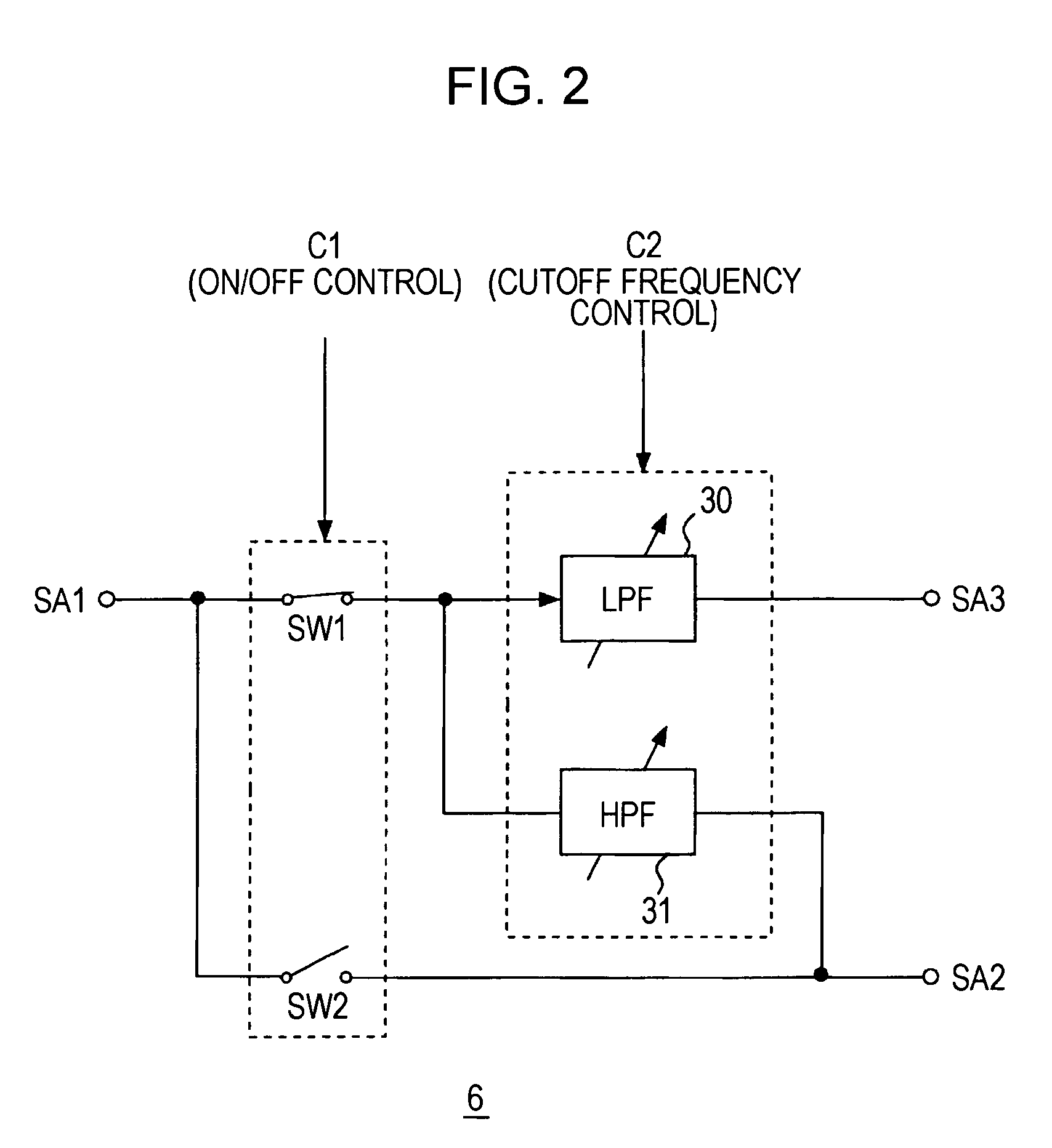
[0040]The spectrum analysis / control unit 4 performs spectrum analysis of the input noise audio signal and detects the level of each frequency band. As described below, the spectrum analysis / control unit 4 also controls the operation of the band dividing unit 6 and the pitch shift unit 7 in accordance with the de...
second embodiment
[0111]The configuration of an audio apparatus 1 according to a second embodiment is illustrated in FIG. 7. The components that are same as those in FIG. 1 will be indicated by the same reference numerals, and descriptions thereof will not be repeated.
[0112]In such a case, an audio signal SA1 from an audio reproduction unit 5 is directly supplied to a combining unit 8 and is supplied to a bandpass tunable filter unit 11.
[0113]The bandpass tunable filter unit 11 includes, for example, a switch SW1 and a bandpass tunable LPF 30, as shown in FIG. 8. The switch SW1 is turn on or off by a control signal C1 from a spectrum analysis / control unit 4. The cutoff frequency of the bandpass tunable LPF 30 is variably set by a control signal C2 from the spectrum analysis / control unit 4.
[0114]The output from the bandpass tunable LPF 30 is supplied to a pitch shift unit 7 as an audio signal SA3 of a frequency band subjected to a pitch shifting.
[0115]At the pitch shift unit 7, a pitch shift signal SA...
third embodiment
[0126]A third embodiment will be described with reference to FIG. 9. The components that are the same as those in FIG. 1 will be represented by the same reference numerals, and descriptions thereof will not be repeated.
[0127]The configuration illustrated in FIG. 9 is the same as that illustrated in FIG. 1, except that a low-band noise detection / control unit 14 is provided instead of the spectrum analysis / control unit 4. The low-band noise detection / control unit 14 is a section that performs simple spectral analysis. The low-band noise detection / control unit 14 extracts only the low frequency band of the noise audio signal collected at a microphone 2 using an LPF having a cutoff frequency of a specific frequency fx and detects the noise level of the extracted frequency band. Then, the low-band noise detection / control unit 14 determines whether or not masking has occurred according to the detected noise level.
[0128]An audio signal SA1 from an audio reproduction unit 5 is supplied to a...
PUM
 Abstract
Description
Claims
Application Information
 - R&D
- Intellectual Property
- Life Sciences
- Materials
- Tech Scout
- Unparalleled Data Quality
- Higher Quality Content
- 60% Fewer Hallucinations
Browse by: Latest US Patents, China's latest patents, Technical Efficacy Thesaurus, Application Domain, Technology Topic, Popular Technical Reports.
© 2025 PatSnap. All rights reserved.Legal|Privacy policy|Modern Slavery Act Transparency Statement|Sitemap|About US| Contact US: help@patsnap.com


