
Wireless system for epilepsy monitoring and measurement

a wireless system and epilepsy technology, applied in the field of epilepsy monitoring and measurement devices, can solve the problems of inconvenient and interfering with the existence of a tether, prior wireless systems for monitoring eeg signals in patients are not meeting the wide variety of needs, etc., and achieve the effect of increasing freedom for the monitored patient and low power loss

Active Publication Date: 2012-04-24
TECH MEDICAL INSTR +1
View PDF5 Cites 10 Cited by
  • Summary
  • Abstract
  • Description
  • Claims
  • Application Information

AI Technical Summary

Benefits of technology

The present invention is a wireless system for monitoring brain tissue. It consists of multiple electrodes placed on the brain tissue, a main circuitry placed outside the body and using infrared energy to transmit power and receive data, and remote circuitry that sends and receives the data using infrared energy. The remote circuitry captures EEG signals from the electrodes and measures the electrical impedance of each electrode. It also includes a battery for additional power and a circuit-loop-interrupting element to prevent MRI-induced damage. The system can provide MRI-safe monitoring and can stimulate brain tissue. The "technical effect" of this invention is to provide a safe and effective way to monitor brain tissue with high resolution and bandwidth.

Problems solved by technology

The existence of a tether is both interfering and inconvenient.
Prior wireless systems for monitoring EEG signals in patients fall short of meeting the wide variety of needs which characterize the complex challenges facing the medical community in providing such diagnosis and treatment today.

Method used


Image

  • Wireless system for epilepsy monitoring and measurement
  • Wireless system for epilepsy monitoring and measurement
  • Wireless system for epilepsy monitoring and measurement

Examples


Embodiment Construction

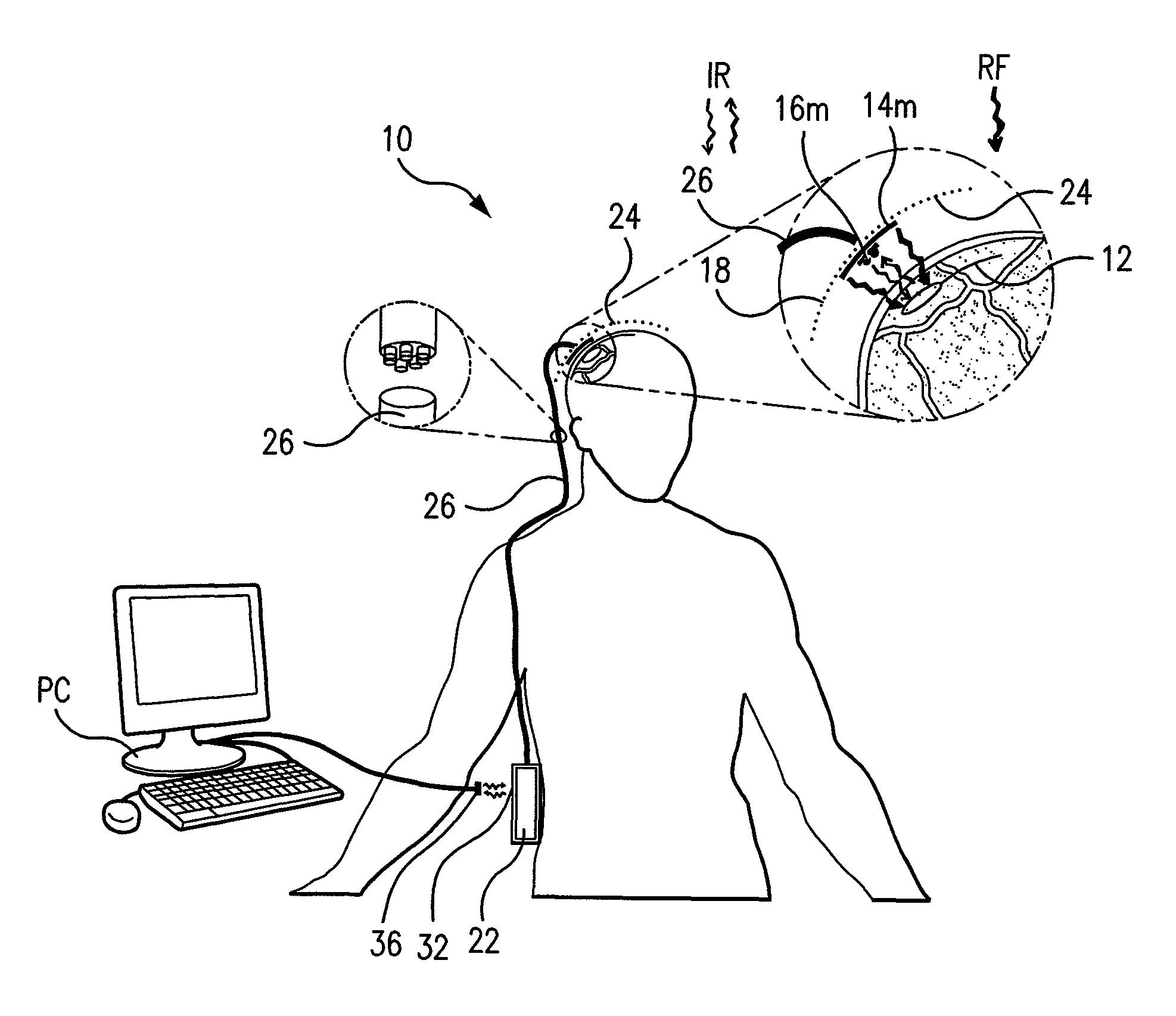
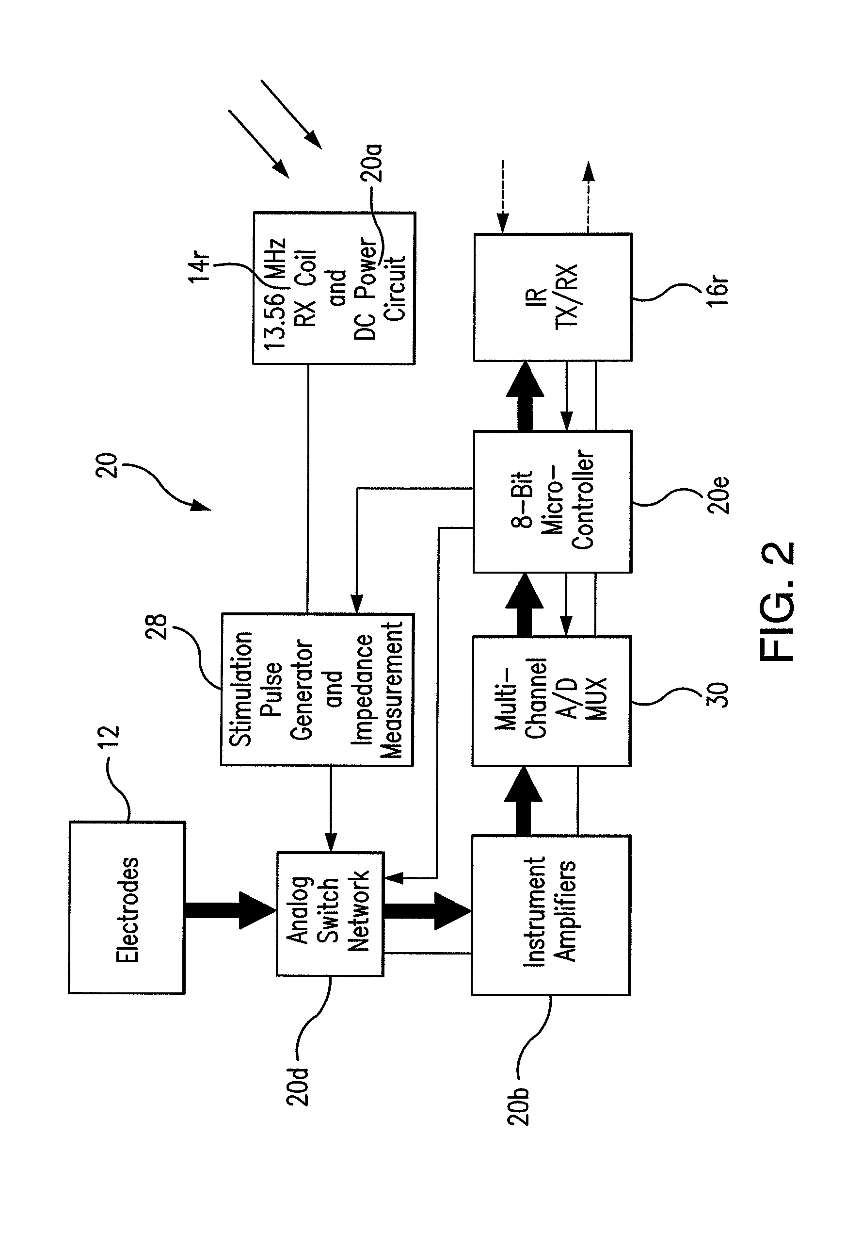
[0053]FIG. 1 is a schematic diagram of one embodiment of the inventive wireless system for monitoring the brain tissue of a patient. A plurality of electrodes 12 are implanted in the human brain to abut brain tissue, and are positioned to monitor EEG signals where the physician performing the procedure determines are regions of interest within the patient's brain. (In this document, reference number 12 is used when referring to either a single selected electrode or the plurality of electrodes. In each case, the single / plural context is clear.) Electrodes 12 are connected to an implanted device containing remote circuitry 20. Included as part of remote circuitry 20 is an RF inductive receive coil 14r connected to TP1 and TP2 in FIGS. 4 and 10. One embodiment of coil inductive receive coil 14r is shown in FIG. 4A. Also included in remote circuitry 20 is an infrared transceiver 16r (shown in FIG. 6) for transmitting and receiving data with an infrared signal across the skin 18 of the p...


PUM


Abstract

A wireless system for monitoring a patient's brain tissue including (1) a plurality of electrodes abutting brain tissue, (2) main circuitry outside the patient's body to transmit power at radio frequencies and send / receive data using infrared energy, and (3) subcutaneously-implanted remote circuitry connected to the electrodes and configured to (a) receive transmitted RF power, (b) capture and digitize EEG signals from the electrodes, and (c) send / receive data to / from the main circuitry using IR energy, including sending digitized EEG signals from each electrode to capture the full bandwidth of each EEG signal. The system preferably includes circuitry to measure the electrical impedance of each electrode for real-time monitoring of the condition of the electrode / tissue interfaces to enhance interpretation of captured EEG signals.

Description

RELATED APPLICATIONS[0001]This application claims the benefit of U.S. Provisional Patent Application Ser. No. 61 / 040,650, filed Mar. 29, 2008, and U.S. Provisional Patent Application No. 60 / 963,012, filed Aug. 1, 2007, the entire contents of which are incorporated herein by reference.FIELD OF THE INVENTION[0002]The invention relates generally to devices for monitoring and mapping of brain activity in epilepsy patients and patients with other neurological disorders and, more particularly, to systems which facilitate accurate measurement for periods of time through the use of implanted devices and electrodes.BACKGROUND OF THE INVENTION[0003]Accurate sensing of intracranial electrical activity, such as for determining epileptogenic foci or otherwise, often may require use of a plurality of brain contacts. Epileptogenic mapping is one example of the use of electrical devices with tissue-engagement contacts. Examples of two kinds of intracranial electrical contact devices are depth probe...

Claims


Application Information

Patent Timeline
Patent Type & Authority Patents(United States)
IPC IPC(8): A61N1/00A61B5/04
CPCA61B5/0017A61B5/0476A61B5/4094A61B5/369
Inventor PUTZ, DAVID A.JOSHI, BHARAT S.LANNING, BRUCENOLAN, JAMES A.NUEBEL, GREGORY J.SPENCER, DENNIS D.ZAVERI, HITTEN P.
Owner TECH MEDICAL INSTR
Learn More