Face mask

a face mask and mask technology, applied in the field of facial skin cleaning, can solve the problems of laborious and inconvenient strip fastening, uneven electric current distribution across the face to be treated, etc., and achieve the effect of cleaning the face skin and being easy to remov

Inactive Publication Date: 2012-04-24
SINIKKA ANNELEENA LEHTOLUOTO +1
View PDF19 Cites 6 Cited by
  • Summary
  • Abstract
  • Description
  • Claims
  • Application Information

AI Technical Summary

Benefits of technology

[0007]According to another embodiment, the edge portion of the face mask is stretchable such that the mask can be tightened while being fitted.
[0012]The absorbent layer is thin. The thickness of the absorbent material is preferably 3 mm or less, more preferably 2 mm or less, and most preferably 1 mm or less. The thin absorption layer can be easily shaped according to the contours of the skin. The thin fibre in itself is light, so it stays on the skin more easily. However, the absorption layer should be sufficiently absorbent and thick so as to be capable of receiving at least an amount of liquid corresponding to the amount of liquid to be transferred into the skin at the beginning of a treatment period. The skin is capable of receiving only a certain amount of liquid. At least this amount of liquid, however, should be absorbed into the fibre so as to prevent the skin from drying due to the treatment period. After the liquid has been transferred into the skin, the thin absorption layer should be dry enough in order to be capable of receiving liquid and impurities back from the moistened skin, assisted by electric current.
[0016]The topmost layer of the face mask may be a plastic film. The different layers may be attached to one another e.g. by ultrasound. In such a case, the electrically conductive layer resides between the absorption layer and the surface layer. The electrically conductive layer may also be provided directly on the underside of an upper plastic layer. The electrically conductive layer may also be perforated. In such a case, the topmost layer may be attached to the lowest layer by heating the plastic layer such that the topmost layer becomes attached to the lowest absorption layer through the perforations provided in the electrically conductive layer. Such a manner of attachment enables the use of glues to be avoided when attaching the different layers to one another. The attachment may also be implemented by using meltable glue dots, silicon dots, or plastic rivets. The absorption layer and the upper layers may also be attached to one another by the user. In such a case, one layer is provided with a glue portion to receive and attach the layers to one another. Such a gluing procedure implemented by the user may be preferable e.g. when liquid has already been absorbed into the absorption layer.
[0018]The gripping means may be made of an adhesive which has been covered with a removable cover paper. In addition to the edge portion, the removable cover paper may cover the entire face mask, in which case it keeps the absorption layer clean during storage. A cover paper which covers the entire face mask is preferable particularly when the cleansing liquid has been absorbed into the face mask already while manufacturing the face mask. The cleansing liquid may also be gel-like, so that it sets tightly onto the cover paper, enhancing preservability. Such a gripping procedure may also be implemented by a two-sided sticker tape to be provided in the edge portion.

Problems solved by technology

The user may find such a strip fastening laborious and inconvenient.
In addition, users have different faces, wherefore the stiffer portion does not enable the lower portions to be placed against the skin evenly; therefore, electric current does not become evenly distributed across all the areas to be treated.

Method used


Image

  • Face mask
  • Face mask
  • Face mask

Examples


first embodiment

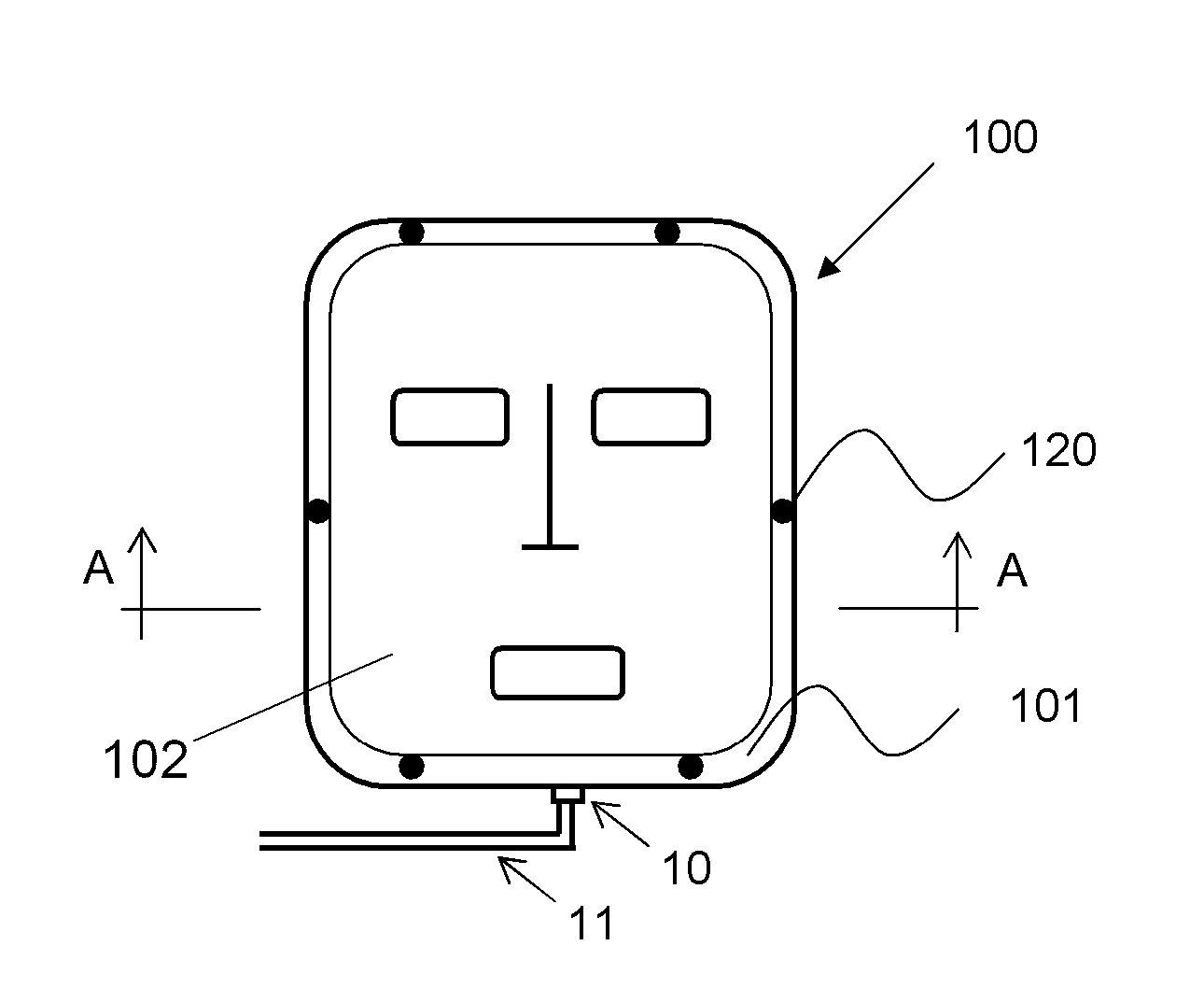
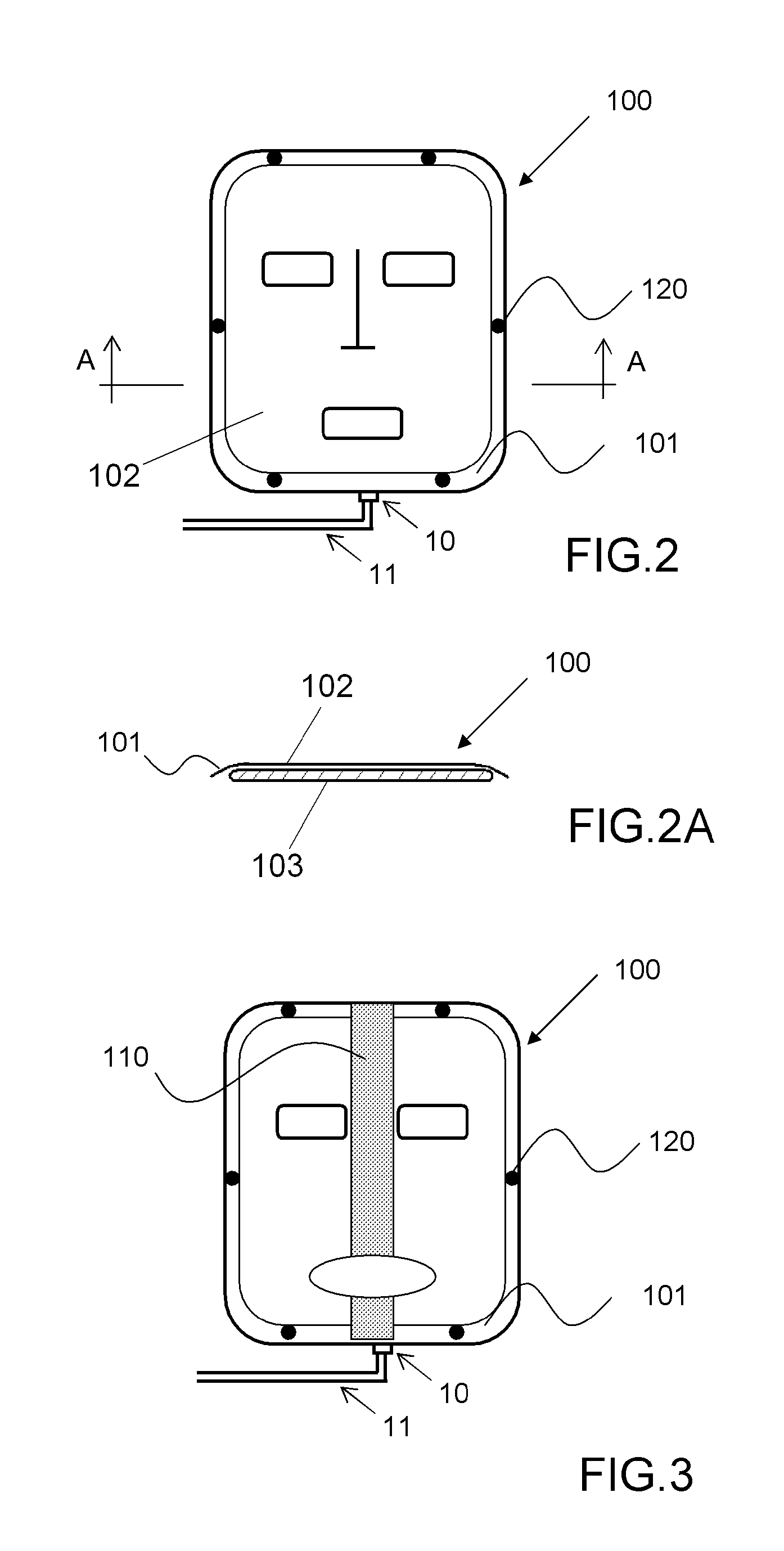
[0031]FIG. 3 shows a face mask 100 according to the present invention. In addition to the edge portion 101, the face mask herein comprises an isolation portion 110. The purpose of the isolation portion 110 is to prevent electric current from transferring between electrodes, instead of the skin, in the face mask 100. It is to be noted that the size and shape of the isolation portion may vary, depending on the shapes of the electrodes. The edge portion may also be made of a plastic material. In such a case, the uppermost plastic layer is larger than other layers. The face mask can be fitted onto the user's face by means of the stretchable uppermost plastic layer.

second embodiment

[0032]FIG. 4 shows a face mask according to the present invention. The face mask 100 is provided with two alignment portions 121 and 122. At the nose of the user, the face mask has a first alignment portion 121 provided with gripping means 120 for adjusting and fitting the face mask according to the nose of the user of the face mask. A second alignment portion 122 is provided at the chin of the user. The purpose of the second alignment portion is to adjust the mouth opening of the face mask at the mouth of the user. The width and length of the alignment portions may vary.

third embodiment

[0033]FIG. 5 shows a face mask according to the present invention. The face mask 100 is a partial face mask such that it covers a certain area of the face. The partial face mask disclosed herein covers a lower part of the face.


PUM


Abstract

A face mask for cleansing of facial skin. The face mask 100 comprises two or more electrodes 22, 23 to which an electric cleansing signal generated by a cleansing signal generator of the face mask is conveyable, the electrodes provided in the face mask 100 being arranged as electrode pairs 24 which comprise a positive electrode 22 and a negative electrode 23 such that all electrode pairs 24 reside in the face mask 100 substantially in the facial area. The face mask is characterized in that the outer edge of the face mask 100 has an edge portion 101 provided with gripping means 120 for fitting the face mask onto the skin of a user of the face mask.

Description

BACKGROUND OF THE INVENTION[0001]The invention relates to cleansing of skin, and particularly to a face mask for cleansing of facial skin, the face mask being provided with two or more electrodes to be connected to a cleansing signal generator which generates a cleansing signal.[0002]A face mask according to FIG. 1 is previously known, which comprises two or more electrodes 22, 23 to which an electric cleansing signal generated by a cleansing signal generator 1 external to the face mask is conveyable, the electrodes provided in the face mask being arranged as pairs of electrodes comprising a positive electrode and a negative electrode and residing in the face mask. Furthermore, the face mask comprises a fibre layer to be placed against the skin. The fibre material has good absorption properties, enhanced by electric current provided by the electrodes.[0003]The face mask comprises a stiffer outermost portion which presses the face mask against a user's face. The stiffer portion may b...

Claims


Application Information

Patent Timeline
Patent Type & Authority Patents(United States)
IPC IPC(8): A61N1/18A61KA61N1/32
CPCA61N1/328A41G7/00A61N1/32
Inventor LEHTOLUOTO, EEVA LIISA
Owner SINIKKA ANNELEENA LEHTOLUOTO
Why Eureka
Try Eureka