System and method to generate electricity

a technology of electricity generation and system, applied in steam engine plants, machines/engines, mechanical equipment, etc., can solve problems such as loss of efficiency and impact on the economic value of electricity generation

Inactive Publication Date: 2012-05-01
GENERAL ELECTRIC CO
View PDF19 Cites 84 Cited by
  • Summary
  • Abstract
  • Description
  • Claims
  • Application Information

AI Technical Summary

Benefits of technology

[0004]According to one aspect of the invention, a split heat recovery steam generator (HRSG) arrangement to reduce emissions in exhaust gases emitted from a turbomachine system to generate electricity including a compressor, a combustor fluidly coupled to and disposed downstream from the compressor and a turbine fluidly coupled to and disposed downstream from the combustor to receive combustion gases and fluidly connected to the compressor to receive cooling and leakage fluid is provided. The arrangement includes a first HRSG coupled to the turbine and thereby receptive of a portion of the exhaust gases to deliver the portion of the exhaust gases to the compressor, a second HRSG coupled to the turbine and thereby receptive of a remaining portion of the exhaust gases, which includes an NOx catalyst and a CO catalyst sequentially disposed therein to remove NOx and CO from the exhaust gases and an air injection apparatus to inject air into the second HRSG between the NOx catalyst and the CO catalyst to facilitate CO consumption at the CO catalyst.
[0005]According to another aspect of the invention, a system to generate electricity is provided and includes a turbomachine. The turbomachine includes a compressor, a combustor fluidly coupled to and disposed downstream from the compressor and a turbine fluidly coupled to and disposed downstream from the combustor to receive combustion gases and fluidly connected to the compressor to receive cooling and leakage fluid. The system further includes a first heat recovery steam generator (HRSG), coupled to the turbine and thereby receptive of a portion of exhaust gases output from the turbine, the first HRSG being configured to deliver the portion of the exhaust gases to the compressor, a second HRSG, coupled to the turbine and thereby receptive of a remaining portion of the exhaust gases output from the turbine, which includes an NOx catalyst and a CO catalyst sequentially disposed therein to treat the received exhaust gases and an air injection apparatus to inject air into the second HRSG between the NOx catalyst and the CO catalyst to facilitate CO consumption at the CO catalyst.

Problems solved by technology

Often however reduction of pollutants is directly connected to a loss of efficiency that impacts the economic value of electricity generation.

Method used


Image

  • System and method to generate electricity
  • System and method to generate electricity
  • System and method to generate electricity

Examples


Embodiment Construction

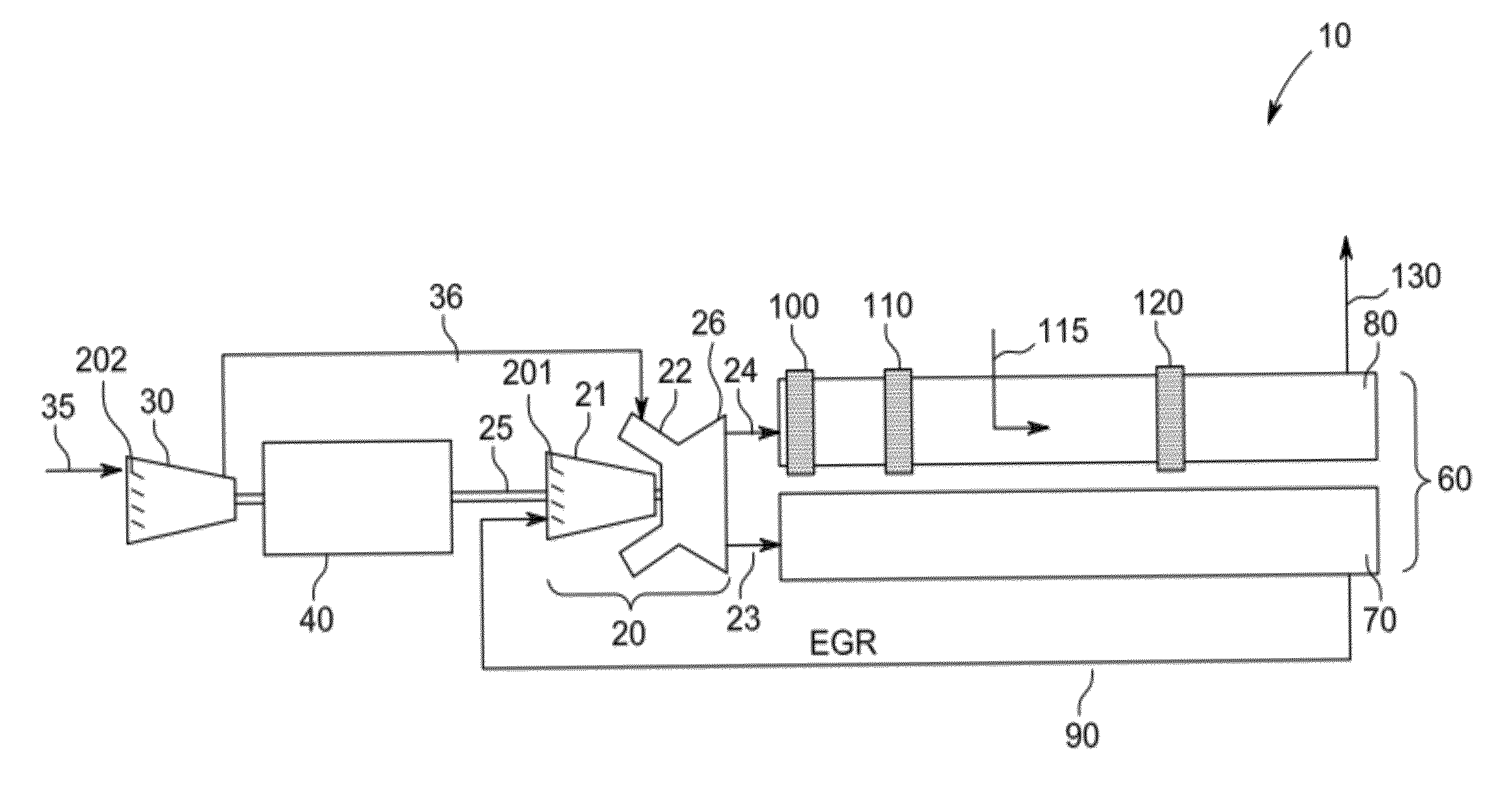
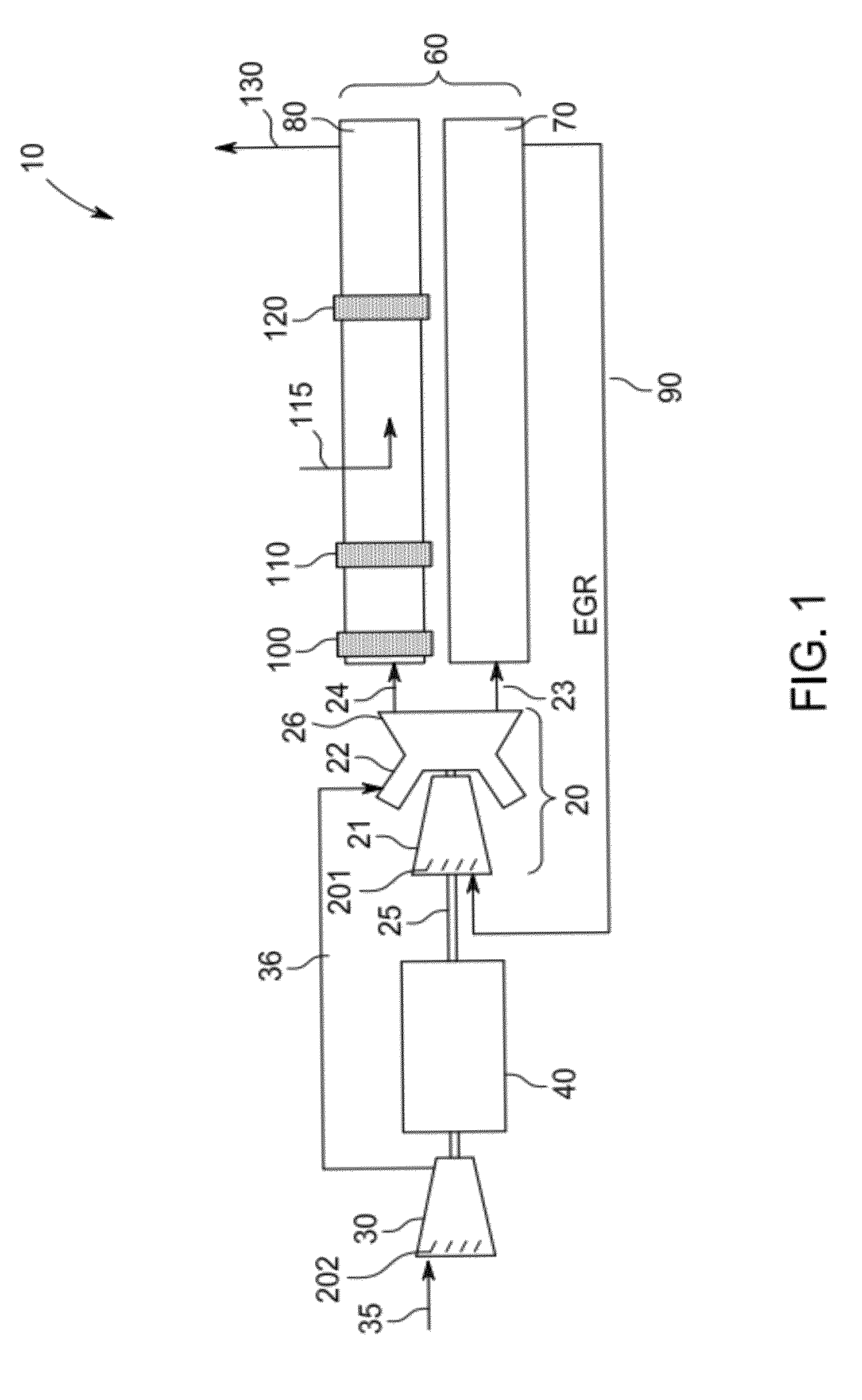
[0014]With reference to FIGS. 1 and 2, a system 10 is provided to generate electricity with reduced emissions. More particularly, the system 10 is provided to generate electricity with little or no Oxides of Nitrogen (NOx) or Carbon Monoxide (CO) pollutant emissions. The system 10 includes a turbomachine, such as a gas turbine (GT) engine 20, a split heat recovery steam generator (HRSG) arrangement 60 having a first HRSG 70 and a second HRSG 80 and an air injection apparatus 115. In the GT engine 20, a compressor 21 compresses exhaust recirculated from the second HRSG 80, which is supplied to a combustor 22 that is fluidly coupled to and disposed downstream from the compressor 21. The combustor 22 may include at least one or more of dry low NOx (DLN) components and / or late lean injection (LLI) components that serve to reduce NOx emissions. A turbine 26 is coupled to the compressor 21 and the combustor 22 to receive combustion products from the combustor 22 and cooling and leakage fl...


PUM


Abstract

A split heat recovery steam generator (HRSG) arrangement including a first HRSG coupled to a turbine and thereby receptive of a portion of the exhaust gases to deliver the portion of the exhaust gases to a compressor, a second HRSG coupled to the turbine and thereby receptive of a remaining portion of the exhaust gases, which includes an NOx catalyst and a CO catalyst sequentially disposed therein to remove NOx and CO from the exhaust gases and an air injection apparatus to inject air into the second HRSG between the NOx catalyst and the CO catalyst to facilitate CO consumption at the CO catalyst.

Description

BACKGROUND OF THE INVENTION[0001]The subject matter disclosed herein relates to gas turbine engines and, more particularly, to gas turbine engines using stoichiometric exhaust gas recirculation.[0002]In gas turbine (GT) engines, compressed air and fuel are mixed together and combusted to produce high energy fluids that are directed to a turbine section where the fluids interact with turbine buckets to generate mechanical energy, which can be employed to generate power and electricity. In particular, the turbine buckets may rotate a shaft to which an electrical generator is coupled. Within the electrical generator, the shaft rotation induces current in a coil electrically coupled to an external electrical circuit. As the high energy fluids leave the turbine section they can be redirected to a heat recovery steam generator (HRSG) where heat from the fluids can be used to generate steam for steam turbine engines and further power and electricity generation.[0003]With the combustion of ...

Claims


Application Information

Patent Timeline
Patent Type & Authority Patents(United States)
IPC IPC(8): F02C1/00
CPCF02C1/06F02C6/00F05D2270/082F01K11/02Y02E20/16
Inventor DRAPER, SAMUEL DAVID
Owner GENERAL ELECTRIC CO
Why Eureka
Try Eureka