
Vented vial adapter with filter for aerosol retention

a filter and vial technology, applied in the field of vial adapters, can solve the problems of affecting the removal of the adapter, unsatisfactory technique, and limited ability to retain medicament aerosols

Active Publication Date: 2012-05-01
CAREFUSION 303 INC
View PDF28 Cites 165 Cited by
  • Summary
  • Abstract
  • Description
  • Claims
  • Application Information

AI Technical Summary

Benefits of technology

The present invention is directed to a system and method for accessing medicament in rigid vials while retaining aerosols. The system includes a vented vial adapter with a cannula for piercing the vial seal and a first filter device to allow liquid to enter and leave the vial. The vial adapter also has a second filter device to absorb liquid dispersed in gas. The method involves piercing the vial seal with the cannula, conducting non-dispersed liquid and gas out of the vial through the cannula and a vent port, and blocking the passage of non-dispersed liquid with a filter or desiccant. The invention provides a way to safely access and use vial medications while minimizing the risk of aerosol exposure.

Problems solved by technology

The circular housing typically has a plurality of claws or other retaining devices that are positioned under the flange of the vial opening thereby interfering with removal of the adapter from the vial.
However, with some vented vial adapters this technique is unsatisfactory because both the dry or lyophilized material and the diluent can be exposed to ambient airborne bacterial contamination during withdrawal of the reconstituted medical fluid if a filter is not present in the vial adapter.
If this air removed from the vial is channeled to the outside atmosphere, such contamination can lead to problems, among other things, in the form of allergic reactions in the exposed personnel, especially when the air is contaminated with cytotoxic drugs, chemotherapeutic drugs, anesthetics, media containing isotopes, and allergy inducing substances of various kinds.
A disadvantage of prior devices is their limited ability to retain aerosols of medicament.

Method used


Image

  • Vented vial adapter with filter for aerosol retention
  • Vented vial adapter with filter for aerosol retention
  • Vented vial adapter with filter for aerosol retention

Examples


Embodiment Construction

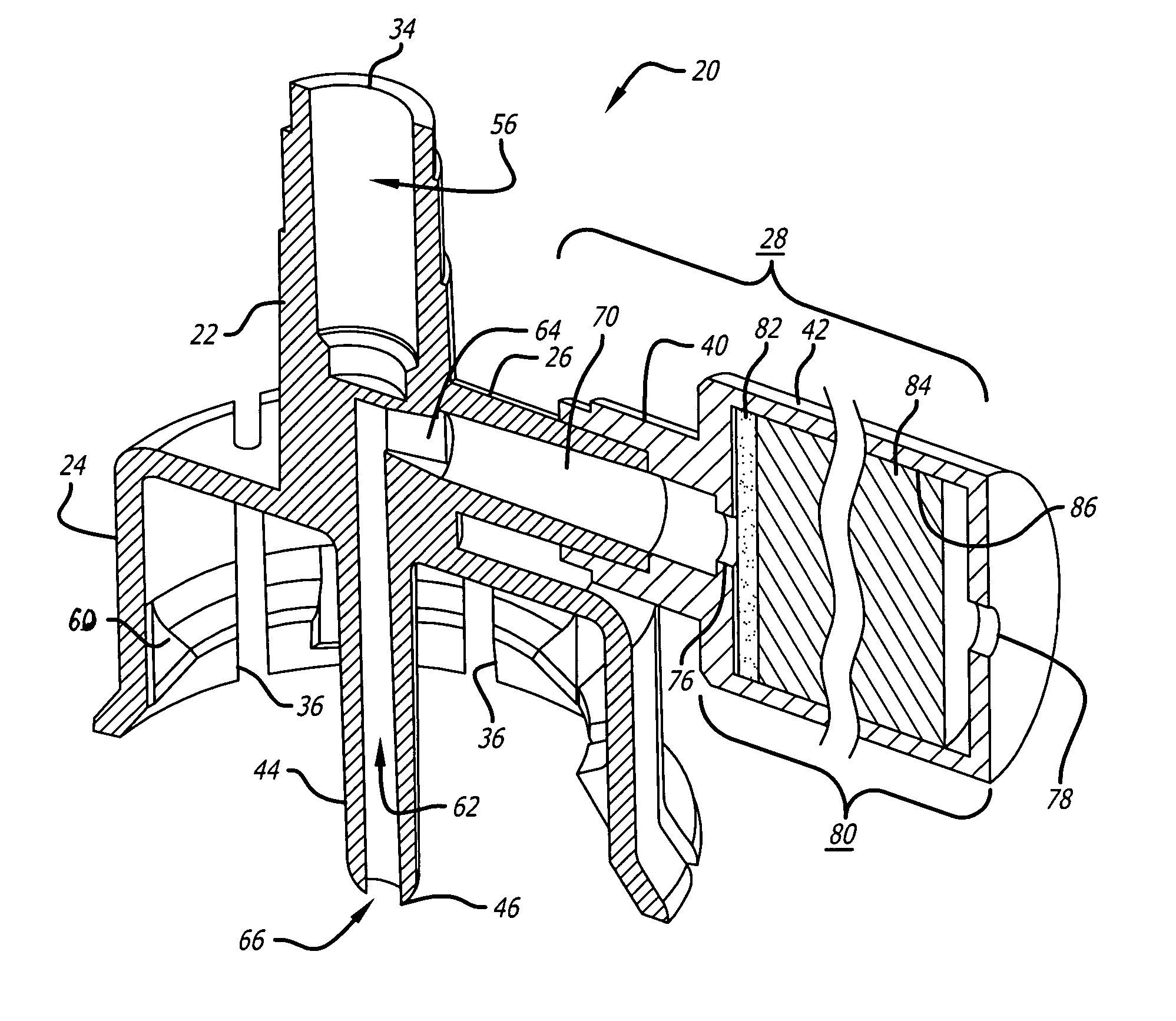
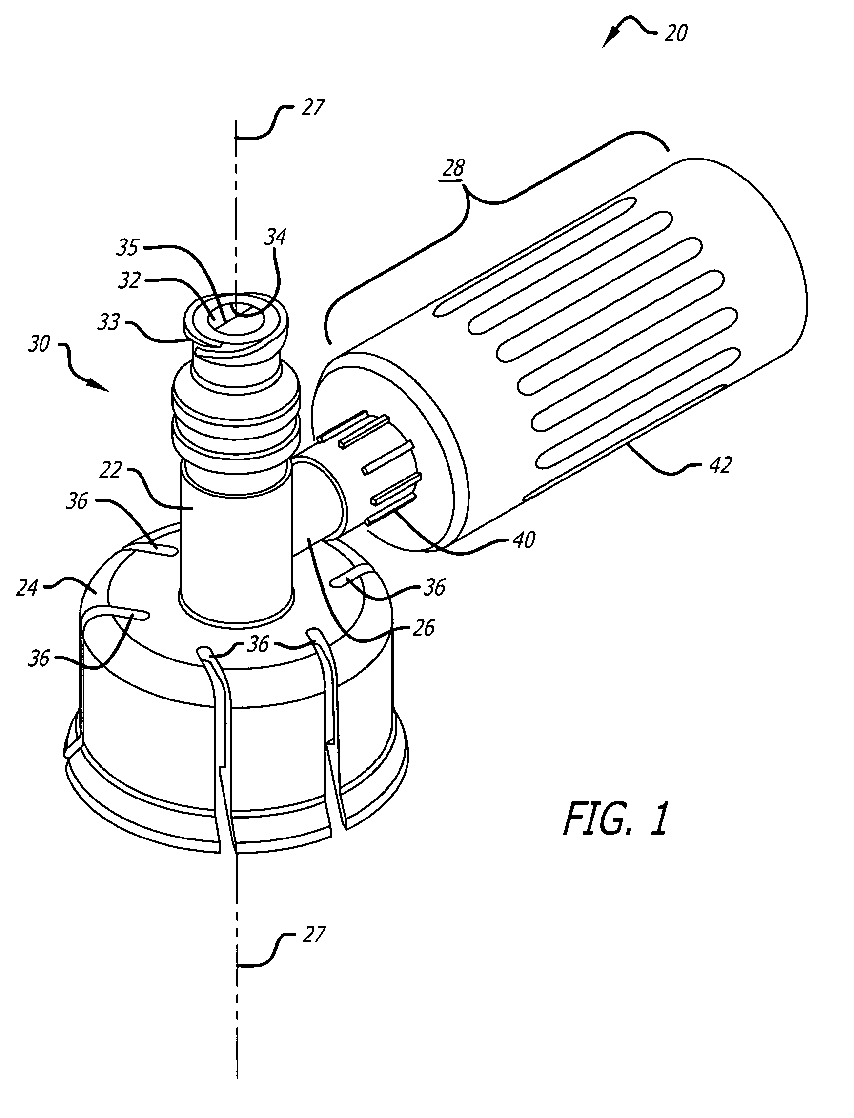
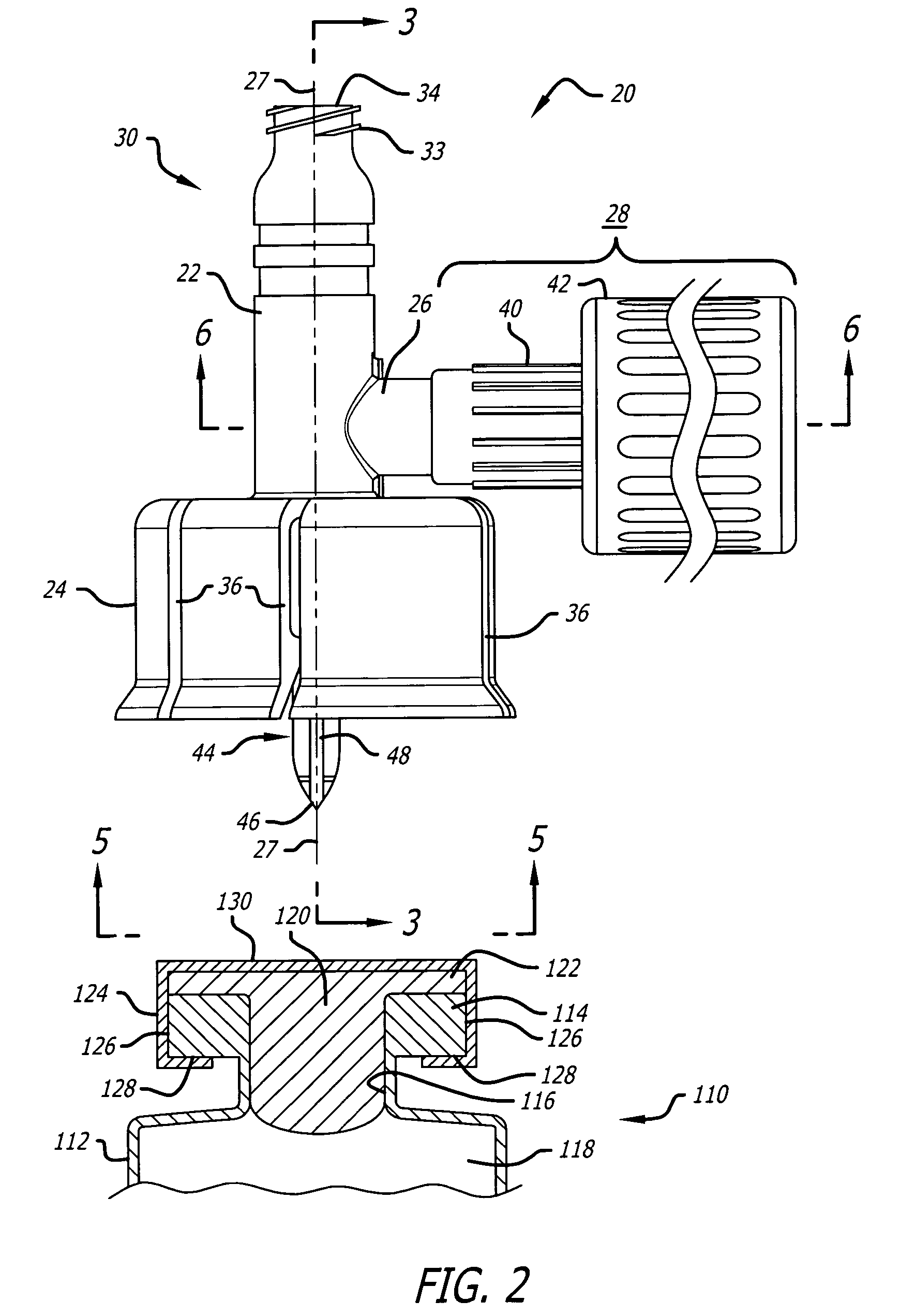
[0031]Referring now to the drawings in more detail in which like reference numerals refer to like or corresponding devices among the views, there is shown in FIGS. 1 and 2 a view of an embodiment of a vial adapter 20 in accordance with aspects of the invention. The vial adapter comprises a body portion 22, a slotted vial attachment housing 24, a vent arm 26 formed at a ninety degree angle to the longitudinal axis 27 of the body portion in this embodiment, a filter apparatus 28, a needle-free valve connector 30 having an internal valve 32, external threads 33 for coupling to a male connector, a female luer connection port 34, and a sharpened cannula 44 for piercing the septa of sealed vials. The needle-free valve connector 30 may take different forms. One form is the SmartSite valve connector from the ALARIS Products division of Cardinal Health, San Diego, Calif. Details on the construction and operation of such a connector are located in U.S. Pat. No. 5,676,346 to Leinsing, incorpor...


PUM


Abstract

A vented vial adapter has a filter attached to a vent arm that includes at least two filter media for suppressing aerosolized medicaments from leaving the vial and suppressing bacteria and other contaminants from entering the vial during reconstitution activities of the medication in the vial. The filter media allows the passage of air to the atmosphere outside the vial for pressure equalization. In another aspect, a third filter medium is used in the vent of the adapter to allow gas to pass in either direction through it, but prevents bacteria and particulate matter in the atmosphere from reaching the second filter device. A first filter is hydrophobic and prevents non-dispersed liquid from reaching the second filter, while conducting liquid dispersed in gas. The second filter absorbs the liquid dispersed in gas.

Description

BACKGROUND OF THE INVENTION[0001]The invention is related generally to vial adapters of the type used in the transfer of medical fluids between a vial and another medical fluid container, and more particularly, to vented vial adapters useful for safe reconstitution and withdrawal of cytotoxic medicament from vials.[0002]Access ports for injecting fluid into or removing fluid from a container, such as a drug vial, are well known and widely used. Conventional seals of drug vials generally involve a pierceable rubber stopper formed of an elastomeric material such as butyl rubber or the like, placed in the opening of the vial. A closure, typically formed of metal, is crimped over the rubber stopper and the flange of the vial to positively hold the stopper in place in the opening of the vial. The closure has an outer size, known as a “finish size.” A sharp cannula is inserted through the rubber stopper to position the distal, open end of the cannula past the rubber stopper to establish f...

Claims


Application Information

Patent Timeline
Patent Type & Authority Patents(United States)
IPC IPC(8): A61M5/32A61B19/00
CPCA61J1/2096A61J2001/201A61J2001/2055A61J2001/2075A61J2001/2082A61J1/201A61J1/2055A61J1/2075A61J1/2082
Inventor YOW, D. GREGORY
Owner CAREFUSION 303 INC
Learn More