
Capacitance to frequency converter

a frequency converter and capacitor technology, applied in the field of electromechanical circuits, can solve the problems of exponential rise in voltage of summing capacitors versus time/cycles, capacitor sensors,

Active Publication Date: 2012-05-01
CYPRESS SEMICON CORP
View PDF226 Cites 40 Cited by
  • Summary
  • Abstract
  • Description
  • Claims
  • Application Information

AI Technical Summary

Problems solved by technology

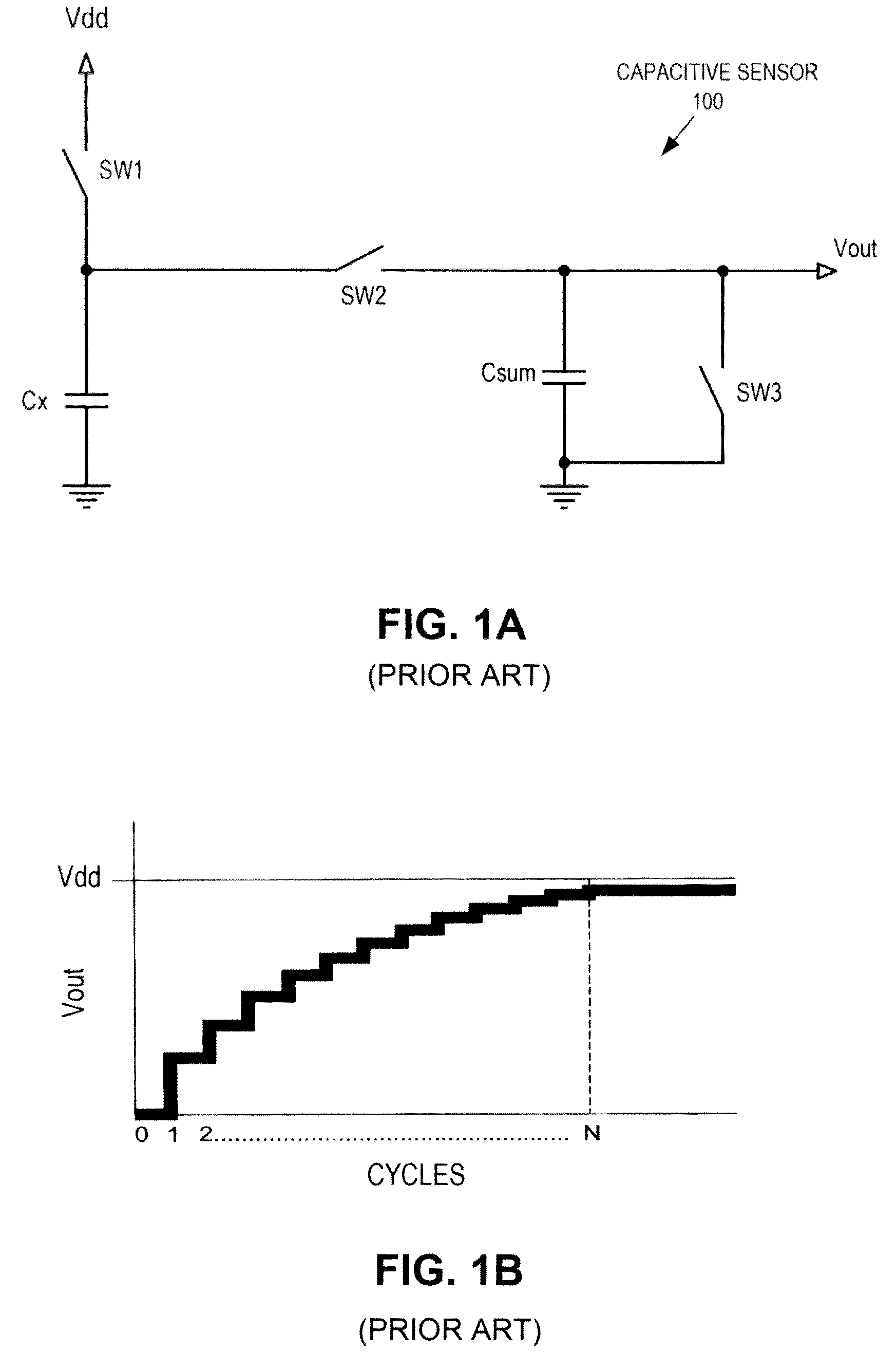
However, conventional capacitance sensors have the disadvantage that that voltage on the summing capacitor Csum rises versus time / cycles in an exponential manner (see FIG. 1B and Equation 1).

Method used


Image

  • Capacitance to frequency converter
  • Capacitance to frequency converter
  • Capacitance to frequency converter

Examples


Embodiment Construction

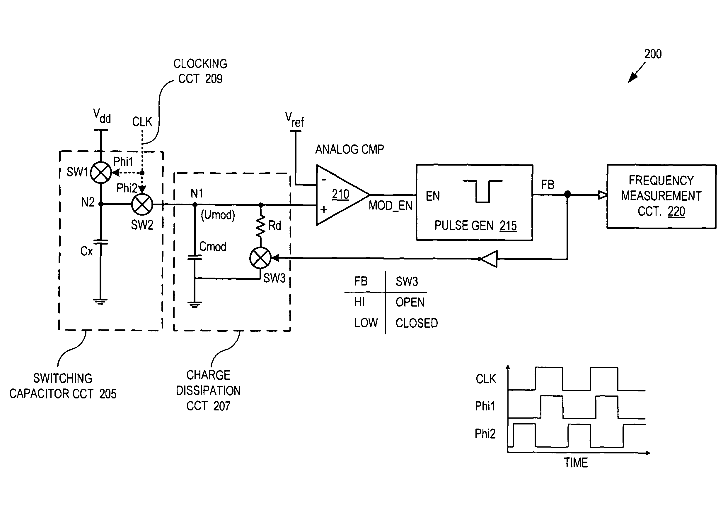
[0018]Embodiments of an apparatus and method of operation for a capacitance to frequency converter are described herein. In the following description numerous specific details are set forth to provide a thorough understanding of the embodiments. One skilled in the relevant art will recognize, however, that the techniques described herein can be practiced without one or more of the specific details, or with other methods, components, materials, etc. In other instances, well-known structures, materials, or operations are not shown or described in detail to avoid obscuring certain aspects.

[0019]Reference throughout this specification to “one embodiment” or “an embodiment” means that a particular feature, structure, or characteristic described in connection with the embodiment is included in at least one embodiment of the present invention. Thus, the appearances of the phrases “in one embodiment” or “in an embodiment” in various places throughout this specification are not necessarily a...


PUM


Abstract

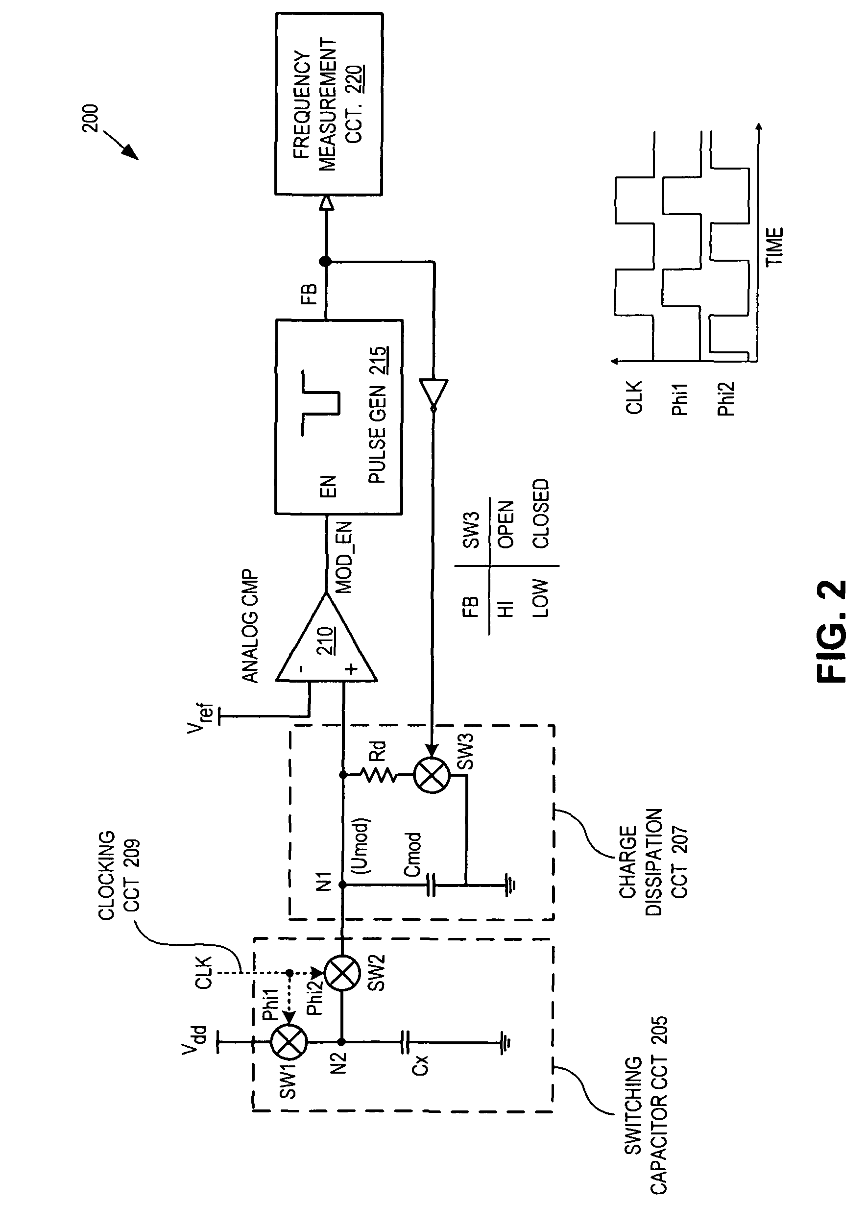
A capacitance to frequency converter includes a switching capacitor circuit, a charge dissipation circuit, a comparator, and a signal generator. The switching capacitor circuit charges a sensing capacitor and transfers charge from the sensing capacitor to a circuit node of the charge dissipation circuit. The comparator is coupled to the charge dissipation circuit to compare a potential at the circuit node to a reference voltage. The signal generator is coupled to an output of the comparator and to the charge dissipation circuit. The signal generator is responsive to the output of the comparator to generate a signal fed back to control the charge dissipation circuit. A frequency of the signal is proportional to a capacitance of the sensing capacitor.

Description

CROSS REFERENCE TO RELATED APPLICATION[0001]This application claims the benefit of U.S. Provisional Application No. 60 / 947,871, filed on Jul. 3, 2007, the contents of which are incorporated herein by reference.TECHNICAL FIELD[0002]This disclosure relates generally to electronic circuits, and in particular but not exclusively, relates to capacitance measurement circuits.BACKGROUND INFORMATION[0003]Capacitance sensors are used to implement a variety of useful functions including touch sensors (e.g., touch pad, touch dial, touch wheel, etc.), determining the presence of an object, accelerometers, and other functions. In general, capacitive sensors are intended to replace mechanical buttons, knobs, and other similar mechanical user interface controls. A capacitive sensor permits eliminating complicated mechanical switches and buttons, providing reliable operation under harsh conditions. Capacitive sensors are widely used in the modern consumer applications, providing new user interface ...

Claims


Application Information

Patent Timeline
Patent Type & Authority Patents(United States)
IPC IPC(8): H03C3/00
CPCG01D5/24H03K17/955G01R27/2605H03K2217/960725H03K2217/96074
Inventor MAHARYTA, ANDRIYKREMIN, VIKTOR
Owner CYPRESS SEMICON CORP
Learn More