Image display method, apparatus, and program

a technology of image display and apparatus, applied in the field of image display methods, apparatuses and programs, can solve the problems of affecting the observation of a region of interest and reducing the observability, and achieve the effect of improving the observability of three-dimensional configuration

Active Publication Date: 2012-05-01
FUJIFILM CORP
View PDF14 Cites 44 Cited by
  • Summary
  • Abstract
  • Description
  • Claims
  • Application Information

AI Technical Summary

Benefits of technology

[0021]According to the image display method, apparatus, and program of the present invention, a luminal or line-like three-dimensional structure is extracted from a three-dimensional image of a target object, then a projection image is generated by projecting a portion of the entirety of the three-dimensional structure on a cross-sectional image of the target object intersecting the three-dimensional structure, the portion being a portion located within a range of a predetermined thickness from a cross-section represented by the cross-sectional image or a portion located within a range of a predetermined distance from a position where the three-dimensional structure is intersecting the cross-sectional image, and the generated projection image is displayed. When attentively observing the intersecting state between the three-dimensional structure and the cross-sectional image, this may provide a more suitable image for observation, in which only a limited region of interest of the three-dimensional structure is superimposed, which may improve observability of the three-dimensional configuration of a target object.

Problems solved by technology

But, when attentively observing the intersecting state between an extracted three-dimensional structure and each cross-sectional image, for example, when checking extraction state of a three-dimensional structure of a blood vessel by sequentially observing the three-dimensional structure at each of the positions where a plurality of cross-sectional images is intersecting in the advancement direction of the structure, the conventional technique described above gives rise to the following problem.
That is, in the conventional technique, the entirety of the extracted three-dimensional structure is superimposed on each cross-sectional image with an indicator, such as a marker or the like attached to the intersecting position, so that as the length of the extracted three-dimensional structure becomes long, or as the structure of the three-dimensional structure becomes complicated, the three-dimensional structure displayed in a superimposed manner becomes large, which hinders observation of a region of interest and observability is degraded.

Method used


Image

  • Image display method, apparatus, and program
  • Image display method, apparatus, and program
  • Image display method, apparatus, and program

Examples


Embodiment Construction

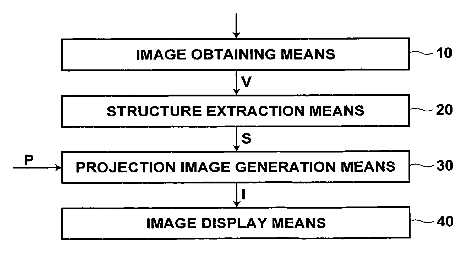
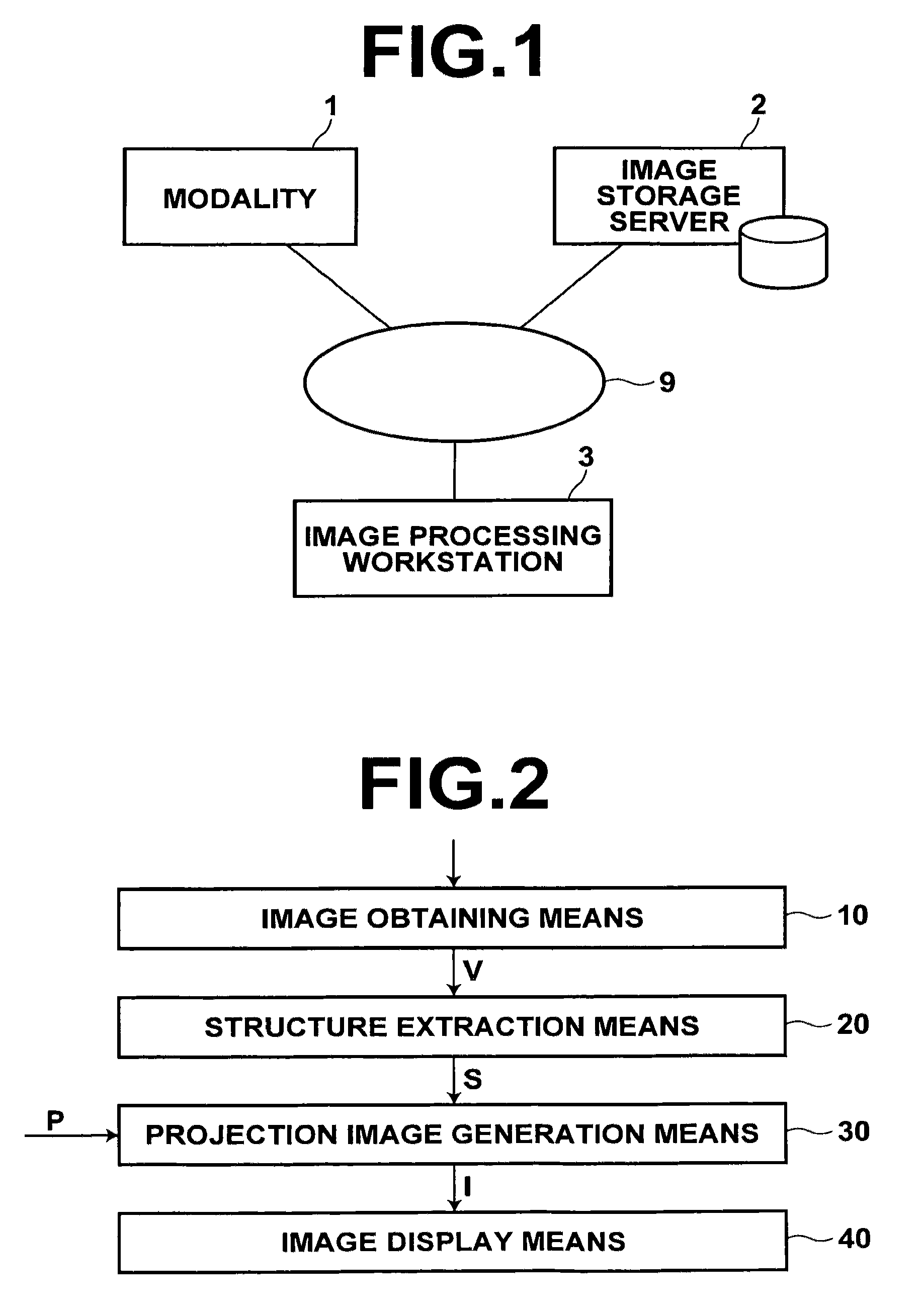
[0036]Hereinafter, an exemplary embodiment of the present invention will be described with reference to the accompanying drawings. FIG. 1 is a hardware configuration diagram of a three-dimensional medical image processing system, illustrating an overview thereof. As illustrated, the system includes a modality 1, an image storage server 2, and an image processing workstation 3, which are communicatably connected with each other through a network 9.

[0037]The modality 1 is used for obtaining a three-dimensional medical image V representing a subject, which is, more specifically, CT equipment, MRI machine, ultrasonic diagnostic equipment, or the like.

[0038]The image storage server 2 is a computer for storing a three-dimensional medical image V obtained by the modality 1 and a medical image generated through image processing in the image processing workstation 3 in an image database and managing them. The image storage server 2 includes a large capacity external storage device, and datab...


PUM


Abstract

Extracting a luminal or line-like three-dimensional structure from a three-dimensional image of a target object, then generating a projection image by projecting a portion of the entirety of the three-dimensional structure on a cross-sectional image of the target object intersecting the three-dimensional structure, the portion being a portion located within a range of a predetermined thickness from a cross-section represented by the cross-sectional image or a portion located within a range of a predetermined distance from a position where the three-dimensional structure is intersecting the cross-sectional image, and displaying the generated projection image.

Description

BACKGROUND OF THE INVENTION[0001]1. Field of the Invention[0002]The present invention relates to an image display method, apparatus, and program for displaying a three-dimensional configuration of a tubular structure extracted from a three-dimensional image of a subject in an easy-to-observe manner. More specifically, the invention is directed to an image display method, apparatus, and program for displaying a three-dimensional configuration of a luminal structure, such as blood vessel, intestine, bronchial tube, or the like in a manner useful for observation.[0003]2. Description of the Related Art[0004]In the medical field, processing for extracting a three-dimensional structure, such as a core line representing structural information of an observation target luminal structure from a three-dimensional medical image of a subject obtained by CT equipment, MRI machine, ultrasonic diagnostic equipment, or the like and displaying the structure in a form useful for observation is perform...

Claims


Application Information

Patent Timeline
Patent Type & Authority Patents(United States)
IPC IPC(8): G06K9/00
CPCG06T19/00G06T2207/10072G06T2207/10088G06T2207/30101
Inventor MASUMOTO, JUNSAKURAGI, FUTOSHI
Owner FUJIFILM CORP
Why Eureka
Try Eureka