Method and device for preparing colloid probe

A technology of probes and colloids, which is applied in the field of probe modification, preparation and processing, can solve the problems of unrepresented device method steps, etc., achieve convenient and fast production operations, improve contrast and observability, and facilitate observation and The effect of the operation

Inactive Publication Date: 2010-02-10
RES CENT FOR ECO ENVIRONMENTAL SCI THE CHINESE ACAD OF SCI
View PDF0 Cites 24 Cited by
  • Summary
  • Abstract
  • Description
  • Claims
  • Application Information

AI Technical Summary

Problems solved by technology

But this method has no representative device and specific method steps

Method used


Image

  • Method and device for preparing colloid probe
  • Method and device for preparing colloid probe
  • Method and device for preparing colloid probe

Examples


preparation example Construction

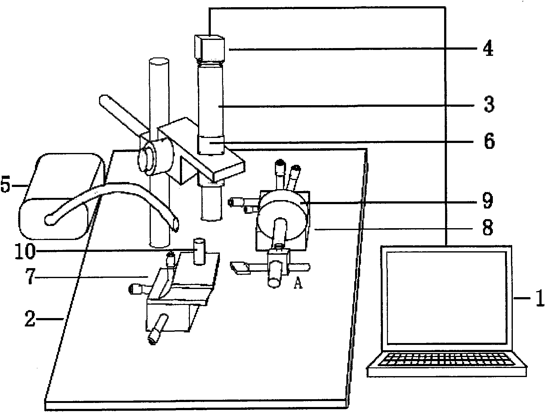
[0053] A device used in the method for preparing a colloidal probe, including a computer 1, an operating table 2, an optical microscope 3, a CCD 4, an external light source 5, a coaxial light source 6, two three-dimensional mobile platforms 7, 8, two copper Column 10, probe holder 18 and infrared oven lamp (not shown in the figure); Wherein,

[0054] Two three-dimensional mobile platforms 7, 8 and a support are fixed on the square operating platform 2, and the support is provided with an optical microscope 3 in the vertical direction, and the optical microscope lens is downward, and the two three-dimensional mobile platforms 7, 8 are respectively located on the optical microscope 3 On both sides directly below; the external light source 5 device box is placed on the side of the square operating table 2, the light source probe is located on the side of the optical microscope 3, and its beam shines on the area under the microscope lens;

[0055] The lens barrel of the optical mi...

Embodiment ( 1

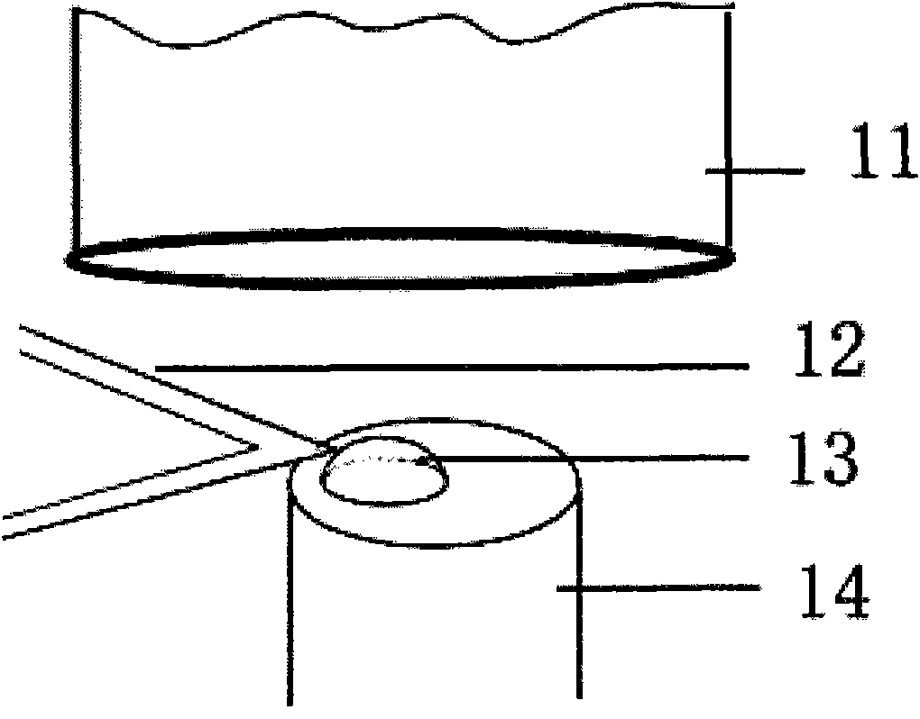
[0086] (1) Disperse silicon microspheres with a diameter of 10 μm in an aqueous solution, disperse them by ultrasonic for 5 minutes, pipette a certain amount of solution with a pipette gun, add it dropwise on the mica sheet of the copper pillar 10, and let it dry naturally. The mica sheet is bonded to the copper pillar through the glass sheet with double-sided adhesive tape. Observe under a high power optical microscope 11 to find suitable microspheres for use.

[0087] (2) Prepare Epotek 377 optical glue drops. Drop a small amount of two-component epoxy resin optical glue on the glass sheet of the copper column in a ratio of 1:1, mix and mix thoroughly with a thin iron wire.

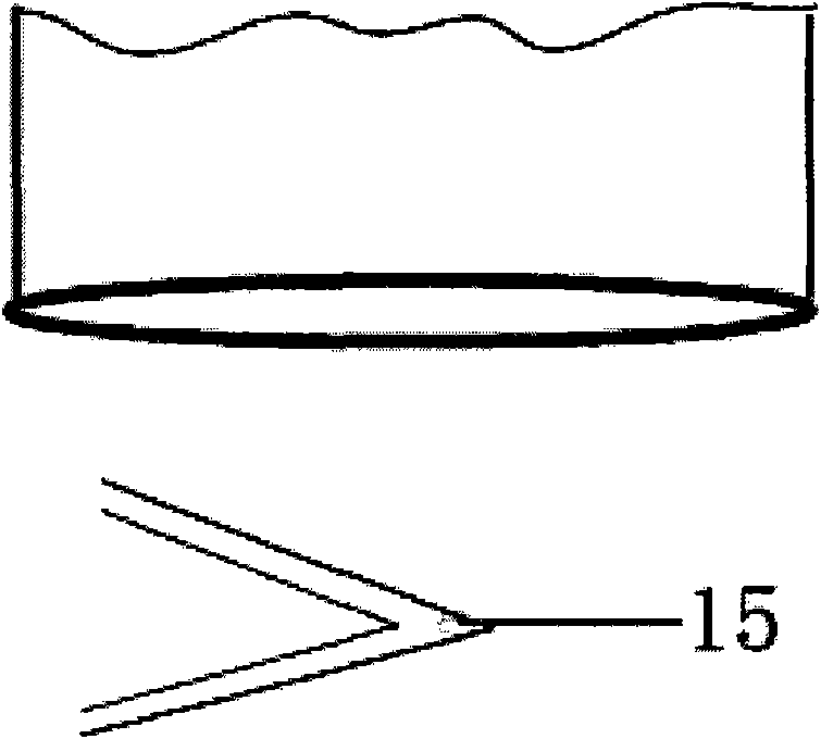
[0088] (3) Install the probe on the probe holder 18 , and then install the probe holder 18 on the bracket 22 of the three-dimensional mobile platform 8 . Under the observation of the high-power optical microscope 11, find the cantilever 12 of the probe, and observe whether the cantilever is damaged to...

Embodiment ( 2

[0097] (1) Disperse silicon microspheres with a diameter of 5 μm in an aqueous solution, disperse them by ultrasonic for 5 minutes, pipette a certain amount of solution with a pipette gun, drop it on the mica sheet of the copper pillar 10, and let it dry naturally. The mica sheet is bonded to the copper pillar through the glass sheet with double-sided adhesive tape. Under the high power optical microscope 11, adjust the magnification of the microscope to 3.5, observe and find suitable microspheres.

[0098] In other steps, the difference from the implementation example (1) is that when using a high-power optical microscope, attention must be paid to adjusting the magnification of the microscope in a timely manner, and gradually zooming in to an appropriate magnification for observation and manipulation of the microparticle bonding process.


PUM

PropertyMeasurementUnit
diameteraaaaaaaaaa

Abstract

The invention discloses a method and a device for preparing a colloid probe, and relates to the probe technology. The colloid probe is prepared by adopting a three-dimensional translation stage to bi-directionally move and adjust the relative positions of a micro cantilever probe and colloid grains or optical adhesive droplets, carrying the micro cantilever probe through a rotary stage and a crossrod rack, adjusting the inclination angle of the micro cantilever probe and sticking the colloid grains to the back of the tip of a probe micro cantilever by using optical adhesive. The method and the device is suitable for preparing the colloid grain probe which uses an atomic force microscope to detect an interaction process of the grains and the surface (grains) so as to acquire a grain-surface (grain) acting force curve. The method and the device are characterized by simple and quick probe preparation operation, and strong practicability, and are suitable for batch manufacturing in a laboratory.

Description

technical field [0001] The invention relates to the technical field of probe modification, preparation and processing, and relates to a method and a device for bonding microparticles on a cantilever under a high-power optical microscope to prepare an atomic force microscope mechanical sensor, that is, a probe. Background technique [0002] The atomic force microscope was invented by Binnig et al. in 1986. The atomic force microscope can detect the shape of atoms and molecules with high resolution and determine the electrical, magnetic and mechanical properties of the surface of objects. conventional tools. The atomic force microscope probe is composed of a matrix, a micro-cantilever, and a needle tip. According to the shape of the micro-cantilever, it can be divided into strip shape and "V" shape. The probe tip is a key part of the atomic force microscope, which directly determines the resolution of the atomic force microscope, thus affecting the application performance of...

Claims


Application Information

Patent Timeline
Patent Type & Authority Applications(China)
IPC IPC(8): B81C5/00G12B21/08G01N13/16
Inventor 葛小鹏臧利杰伍晓红王东升汤鸿霄
Owner RES CENT FOR ECO ENVIRONMENTAL SCI THE CHINESE ACAD OF SCI
Why Eureka
Try Eureka