Automatic lacer for bundles of polymeric fiber

a bundle and polymer technology, applied in the field of modules, can solve the problems of clogging the feeder, dragging the product, and the fibers tending to splay out, so as to reduce the clogging and potential stoppage of downstream equipment, prevent the fiber from clogging, and improve the gas separation or other qualities

Active Publication Date: 2012-05-08
GENERON IGS
View PDF12 Cites 1 Cited by
  • Summary
  • Abstract
  • Description
  • Claims
  • Application Information

AI Technical Summary

Benefits of technology

[0011]The wound fiber bundle is less susceptible to splaying of fibers, thereby reducing clogging and potential stoppages of the downstream equipment. The lacing of the fiber bundle also prevents damage to the fiber, and results in a module having improved gas-separation or other qualities. Thus, the present invention improves both the efficiency of production of hollow fiber membrane modules, and the quality of the modules so produced.
[0012]The present invention has the primary object of providing a method and apparatus for improving the efficiency of a manufacturing process for fiber membrane modules used for gas separation or for other purposes.
[0013]The invention has the further object of reducing the cost of making fiber membrane modules.
[0014]The invention has the further object of enhancing the quality of fiber membrane modules.
[0015]The invention has the further object of improving the selectivity of gas-separation membrane modules.
[0016]The invention has the further object of reducing stoppages of equipment used to make fiber membrane modules, and thereby to improve the productivity of such equipment.

Problems solved by technology

A serious problem with the above-described process is the tendency of the fibers to splay out while being automatically fed to the loom, and / or while being formed into a module.
This splaying causes the fibers to become tangled, resulting in a ragged product.
In some cases, the tangling can clog the feeder, and can require that the loom be stopped.
Such stoppages obviously increase the overall cost of forming the fibers into modules.
Also, it has been found that fiber modules having an excessive proportion of ragged fibers perform relatively poorly.

Method used


Image

  • Automatic lacer for bundles of polymeric fiber
  • Automatic lacer for bundles of polymeric fiber
  • Automatic lacer for bundles of polymeric fiber

Examples


example

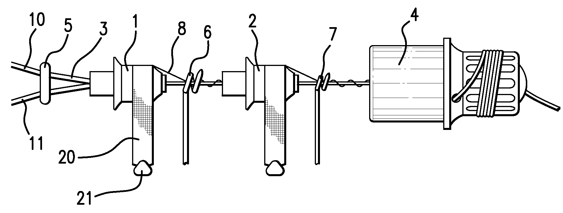
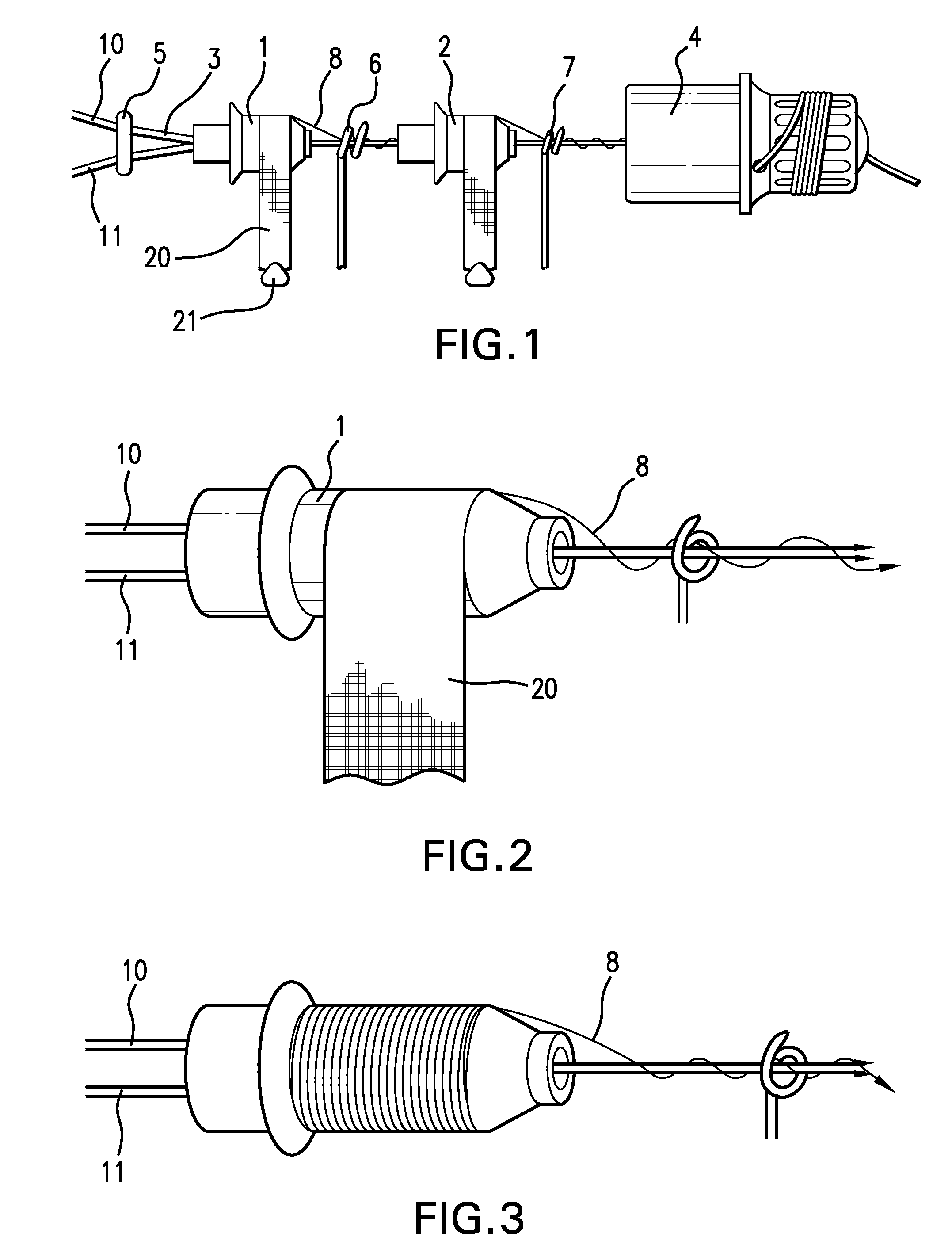
[0042]Three different polymers were used to form fiber membranes. The polymers were selected to be useful in separating oxygen and nitrogen. These polymers were designated as 1, 2, and 3. The fiber bundles made of these materials were tested with either no lacer, a single lacer, or two lacers in series (the latter being what is shown in the figures). That is, these fiber bundles were woven into a fabric mat, and the fabric mat was rolled up and placed in a module housing. The flux of oxygen, and the selectivity between oxygen and nitrogen, were measured and compared. The results are shown in the following table:

[0043]

Oxygen FluxTest Conditions*10−6 (scc / sec · cm2 · cm Hg)O2 / N2 SelectivityFiber 1, no lacer22.044.79Fiber 1, single lacer22.196.42Fiber 2, no lacer23.955.64Fiber 2, two lacers23.886.28in seriesFiber 3, no lacer22.104.64Fiber 3, two lacers20.315.67in series

[0044]For all three fiber materials used, the selectivity was significantly improved with the use of the lacer of the ...


PUM

PropertyMeasurementUnit
weightaaaaaaaaaa
frictionaaaaaaaaaa
energyaaaaaaaaaa

Abstract

An automatic lacer wraps bundles of polymeric fibers with thread, before the bundles are woven into a fabric mat and placed in a housing to form a gas-separation membrane module. A fiber bundle passes through a spool which is previously wound with thread on its outer surface. The thread is attached to the fiber bundle, so that when the bundle is moved through the spool, the thread is pulled from the spool, and automatically becomes wound around the bundle. Threads from two or more spools may be wrapped around the fiber bundle simultaneously. Lacing of the fiber bundles reduces the amount of tangling in the loom feeder, and improves the quality of modules made from the fiber bundles.

Description

CROSS-REFERENCE TO PRIOR APPLICATION[0001]Priority is claimed from U.S. Provisional Patent Application Ser. No. 61 / 119,428, filed Dec. 3, 2008, the entire disclosure of which is incorporated by reference herein.BACKGROUND OF THE INVENTION[0002]The present invention relates to the manufacture of modules containing a plurality of polymeric hollow fibers, for use in gas separation, air dehydration, or for other purposes. Specifically, the present invention provides a method and apparatus for automatically lacing bundles of such fibers, while the fibers are transported through equipment for manufacturing the modules.[0003]It has been known to use a polymeric membrane to separate air into components. Various polymers have the property that they allow different gases to flow through, or permeate, the membrane, at different rates. A polymer used in air separation, for example, will pass oxygen and nitrogen at different rates. The gas that preferentially flows through the membrane wall is c...

Claims


Application Information

Patent Timeline
Patent Type & Authority Patents(United States)
IPC IPC(8): D02G3/00
CPCD03D47/34D03J1/04
Inventor COAN, FREDERICK L.
Owner GENERON IGS
Why Eureka
Try Eureka